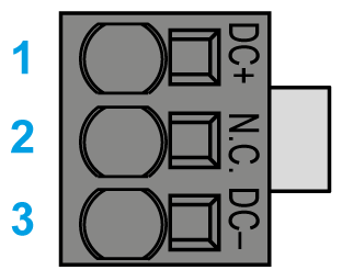
Electrical Connections for the Lexium 62 Power Supply
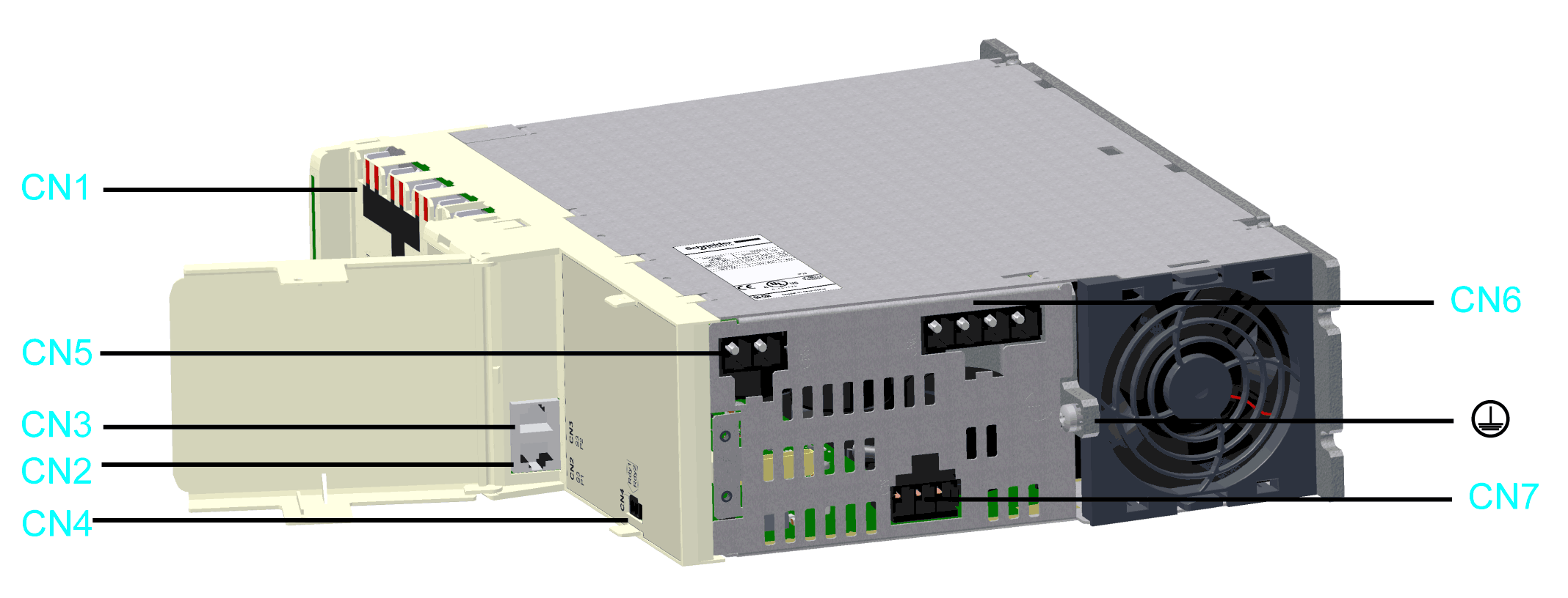
Overview
|
Connector |
Description |
Connection cross-section [mm2] / [AWG] |
Tightening torque [Nm] / [lbf in] |
|---|---|---|---|
|
Bus Bar Module |
– |
2.5 / 22.14 |
|
|
Sercos communication |
– |
– |
|
|
Ready relay output |
0.2...1.5 / 24...16(1) |
– |
|
|
24 Vdc |
0.5…16 / 20...6(1) |
– |
|
|
Mains connection |
0.75…16 / 18...6(1) |
– |
|
|
DC bus output |
0.2…6 / 24...10(1) |
– |
|

|
Protective ground (earth) |
10 / 6 |
3.5 / 30.98 |
|
(1) Gauge required for UL conformance. For further information, refer to Conditions for UL Compliant Use. |
|||
Removable Spring-Clamping Terminal Block Wiring
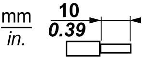
The details in the following table apply for the wiring on the removable spring-clamping terminal block of the CN4 connection.
Overview of the connection cross-sections for the removable spring-camping terminal block CN4 Ready Relay output
|
Rigid wire 
|
Flexible wire 
|
Flexible wire with a wire end sleeve without a plastic sleeve 
|
Flexible wire with a wire end sleeve and plastic sleeve 
|
|---|---|---|---|---|
|
mm2 |
0.2...1.5 |
0.2...1.5 |
0.25...1.5 |
0.25...0.75 |
|
AWG |
24...16 |
24...16 |
23...16 |
23...16 |
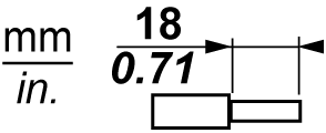
The details in the following table apply for the wiring on the removable spring-clamping terminal block of the CN5, CN6 and CN7 connection.
Overview of the connection cross-sections for the removable spring-clamping terminal block CN5, CN6 and CN7 Mains connection.
|
Rigid wire 
|
Flexible wire 
|
Flexible wire with a wire end sleeve(1) without a plastic sleeve 
|
Flexible wire with a wire end sleeve(1) and plastic sleeve 
|
|---|---|---|---|---|
|
mm2 |
0.75...16 |
0.75...16 |
0.75...16 |
0.75...10 |
|
AWG |
18...6 |
18...6 |
18...6 |
18...8 |
|
(1) Use crimping tools CRIMPFOX 10 S (for wire cross sections 0.75..10 mm², AWG 18..8) and CRIMPFOX 16 S (for wire cross-sections 10...16 mm², AWG 8..6) from Phoenix Contact. |
||||
CN1 - Bus Bar Module
The DC bus voltage and the 24 Vdc control voltage are distributed and the protective conductor is connected via the Bus Bar Module.

|
Pin |
Designation |
Description |
|---|---|---|
|
1 |

|
Protective ground (earth) |
|
2 |
DC- |
DC bus voltage - |
|
3 |
DC+ |
DC bus voltage + |
|
4 |
24 V |
Supply voltage + |
|
5 |
0 V |
Supply voltage - |
CN2/CN3 - Sercos
The Sercos connection is used for the communication between the controller and the Lexium 62 Power Supply.
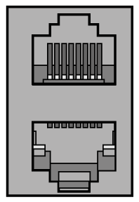
|
Pin |
Designation |
Description |
|---|---|---|
|
1.1 |
Eth0_Tx+ |
Positive transmission signal |
|
1.2 |
Eth0_Tx- |
Negative transmission signal |
|
1.3 |
Eth0_Rx+ |
Positive receiver signal |
|
1.4 |
N.C. |
Reserved |
|
1.5 |
N.C. |
Reserved |
|
1.6 |
Eth0_Rx- |
Negative receiver signal |
|
1.7 |
N.C. |
Reserved |
|
1.8 |
N.C. |
Reserved |
|
2.1 |
Eth1_Tx+ |
Positive transmission signal |
|
2.2 |
Eth1_Tx- |
Negative transmission signal |
|
2.3 |
Eth1_Rx+ |
Positive receiver signal |
|
2.4 |
N.C. |
Reserved |
|
2.5 |
N.C. |
Reserved |
|
2.6 |
Eth1_Rx- |
Negative receiver signal |
|
2.7 |
N.C. |
Reserved |
|
2.8 |
N.C. |
Reserved |
CN4 - Ready Relay Output
Following initialization of the Lexium 62 Power Supply, the Ready output is activated.
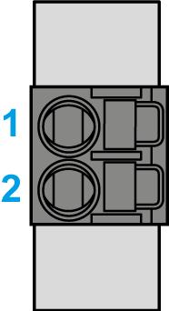
|
Pin |
Designation |
Description |
Note |
|---|---|---|---|
|
1 |
RDY1 |
Indicates that the power supply is operational. |
Potential-free contact |
|
2 |
RDY2 |
CN5 - 24 V
The 24 V input supplies the internal logic assemblies as well as the holding brakes of the axis group, connected to the axis modules.
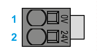
|
Pin |
Designation |
Description |
|---|---|---|
|
1 |
0 V |
Internal supply voltage |
|
2 |
24 V |
The insulation-stripped length of the wires of the 24 V input connector is 18 mm (0.71 in.).
CN6 - Mains Connection
The Power Supply is supplied with voltage via the power connection.
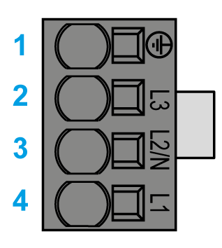
|
Pin |
Designation |
Description |
|---|---|---|
|
1 |

|
Protective ground (earth) |
|
2 |
L3 |
External conductor L3 |
|
3 |
L2/N |
External conductor L2/N |
|
4 |
L1 |
External conductor L1 |
The insulation-stripped length of the wires of the AC infeed connectors is 18 mm (0.71 in.).
