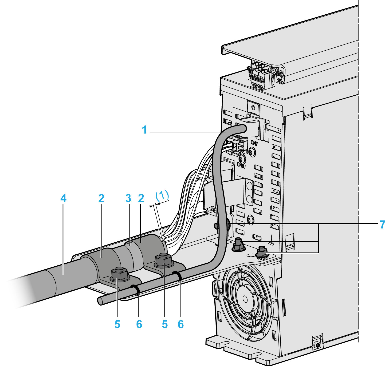
External Shield Connection on the Drive Module LXM62DC13
Presentation

1 Encoder cables
2 Ground clamp
3 Braided shield of cable
4 Motor cables
5 Bolt on the shield plate
6 Strain relief via cable ties
7 Bolt on drive module
(1) Braided shield protrusion (at least 5 mm/0.2 in)
Procedure
To mount the shield plate and to attach the motor/encoder cable, proceed as follows:
|
Step |
Action |
|---|---|
|
1 |
Release and remove the screw-nuts M5 on the bolts (7). |
|
2 |
Fix the shield plate on the bottom side of the drive module, so that the bolts (7) are in the corresponding holes of the shielding. |
|
3 |
Tighten the bolts (7) on the shield plate with the screw nuts M5 (tightening torque: 2.5 Nm / 22 lbf in). |
|
4 |
Connect the motor supply cable (4) to the shield plate so that the end of the cable sheathing is located in the range of the bolt (5). |
|
5 |
Place both ground clamps (2) over the cable sheathing so that the bolts (5) are located in the holes of the ground clamps.
|
|
6 |
Loosely fix the motor supply cable with both screw-nuts M8 above the two ground clamps (2). Result: The motor supply cable can still be moved underneath the ground clamps. |
|
7 |
Finally position the motor supply cable, so that the cable sheathing has a protrusion F to the ground clamp (2) of at least 5 mm (0.2 in.) and the braided shield of the cable (3) is positioned below the first ground clamp (2). |
|
8 |
Tighten the motor supply cable with both screw nuts M8 above the two ground clamps (2) (tightening torque: 6 Nm / 53.10 lbf in). |
|
9 |
Connect the encoder cable (1) to the shield plate and relief the strain by using cable ties (6). |