Setup, Installation, and Maintenance - Wiring Verification
Overview
For mixed applications for the Lexium 62 variants C/D/G and Lexium 62 variants E/F with a two-channel Inverter Enable connection (Application proposal variants C/D/G single-channel jumpered and Application proposal variants C/D/G two-channel with protected wiring) for the Lexium 62 variants C/D/G with a two-channel Inverter Enable connection, a verification of the wiring has to be performed as follows.
Determine Status of Inverter Enable in EcoStruxure Machine Expert Logic Builder
The state of the Inverter Enable input is displayed in the EcoStruxure Machine Expert Logic Builder. This can be used to determine if the drives are correctly wired 1-channel or 2-channel.
1 24 V power supply unit
2 Safety-related switching device
3 24 V external power supply unit
4 Lexium 62 Power Supply
Measuring Procedure
|
Step |
Action |
|---|---|
|
1 |
Wire Inverter Enable channels and connect the connectors to the drives. |
|
2 |
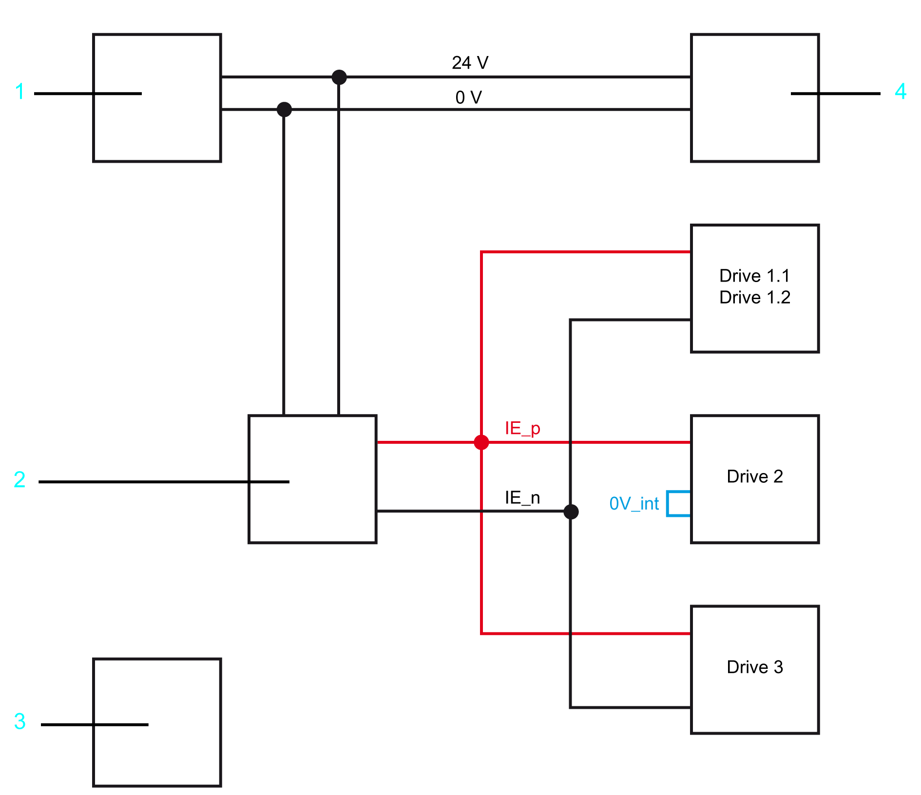
Disconnect the IE_p connection (24 V) for the drives on the safety-related switching device (see step 1 in the following graphic). |
|
3 |
Connect the disconnected IE_p connection (24 V) to an external 24 V power supply unit (see step 2 in the following graphic). |
|
4 |
The negative pole of the Lexium 62 Power Supply has to be connected to the 0 V of the drives (Connector CN5 PIN 1 of the Lexium 62 Power Supply (see step 3 in the following graphic)). |
Verifying the 1-channel wiring
1 24 V power supply unit
2 Safety-related switching device
3 24 V external power supply unit
4 Lexium 62 Power Supply
|
Step |
Action |
|---|---|
|
5 |
Verify the IE (Inverter Enable) state of every individual drive in EcoStruxure Machine Expert Logic Builder. Result: In this case, only the 1-channel drives may be active. |
|
6 |
Record the status values in a table. If necessary, screenshots can also be created in EcoStruxure Machine Expert Logic Builder. |
Example: 1-channel variant
|
Drive |
Connection |
Expected status |
Displayed status |
|---|---|---|---|
|
1.1 |
2-channel |
Off / 0 |
|
|
1.2 |
2-channel |
Off / 0 |
|
|
2 |
1-channel |
On / 1 |
|
|
3 |
2-channel |
Off / 0 |
|
|
This table is used as an example for the documentation and it is mandatory for it to be filled out. In the column "Displayed status" the result, readable in EcoStruxure Machine Expert Logic Builder, has to be entered. |
|||
|
Step |
Action |
|---|---|
|
7 |
Remove the 0 V connection between the Lexium 62 Power Supply and the external power supply unit (see step 4 in the following graphic). |
|
8 |
Disconnect the IE_n connection (0 V) for the 2-channel drives on the safety-related switching device (see step 5 in the following graphic). |
|
9 |
Connect the disconnected IE_n connection (0 V) to the external 24 V power supply unit (see step 6 in the following graphic). |
Verifying the 2-channel wiring
1 24 V power supply unit
2 Safety-related switching device
3 24 V external power supply unit
4 Lexium 62 Power Supply
|
Step |
Action |
|---|---|
|
1 |
Verify the IE (Inverter Enable) status of every individual drive in EcoStruxure Machine Expert Logic Builder. Result: In this case, only the 2-channel drives may be active. |
|
2 |
Record the status values in a table. If necessary, screenshots can also be created in EcoStruxure Machine Expert Logic Builder. |
Example: 2-channel variant
|
Drive |
Connection |
Expected status |
Displayed status |
|---|---|---|---|
|
1.1 |
2-channel |
On / 1 |
|
|
1.2 |
2-channel |
On / 1 |
|
|
2 |
1-channel |
Off / 0 |
|
|
3 |
2-channel |
On / 1 |
|
|
This table is used as an example for the documentation and it is mandatory for it to be filled out. In the column "Displayed status" the result, readable in EcoStruxure Machine Expert Logic Builder, has to be entered. |
|||
|
Step |
Action |
|---|---|
|
3 |
Connect the IE_n connection to the protective switching device again. |
|
4 |
Connect the IE_p connection (24 V) to the protective switching device. |