Free-large Mode Principle Description
Overview
The mode can be used for axis monitoring or labeling in cases where the incoming position of each part has to be known.
Principle
In the mode, the module behaves like a standard up and down counter.
When counting is enabled, the counter counts as follows in:
| Incrementing direction: |
the counter increments. |
| Decrementing direction: |
the counter decrements. |
The counter is activated by a preset edge which loads the preset value.
The current counter is stored in the capture register by using the Capture function.
If the counter reaches the counting limits, the counter will react according to the Limits Management configuration.
Input Modes
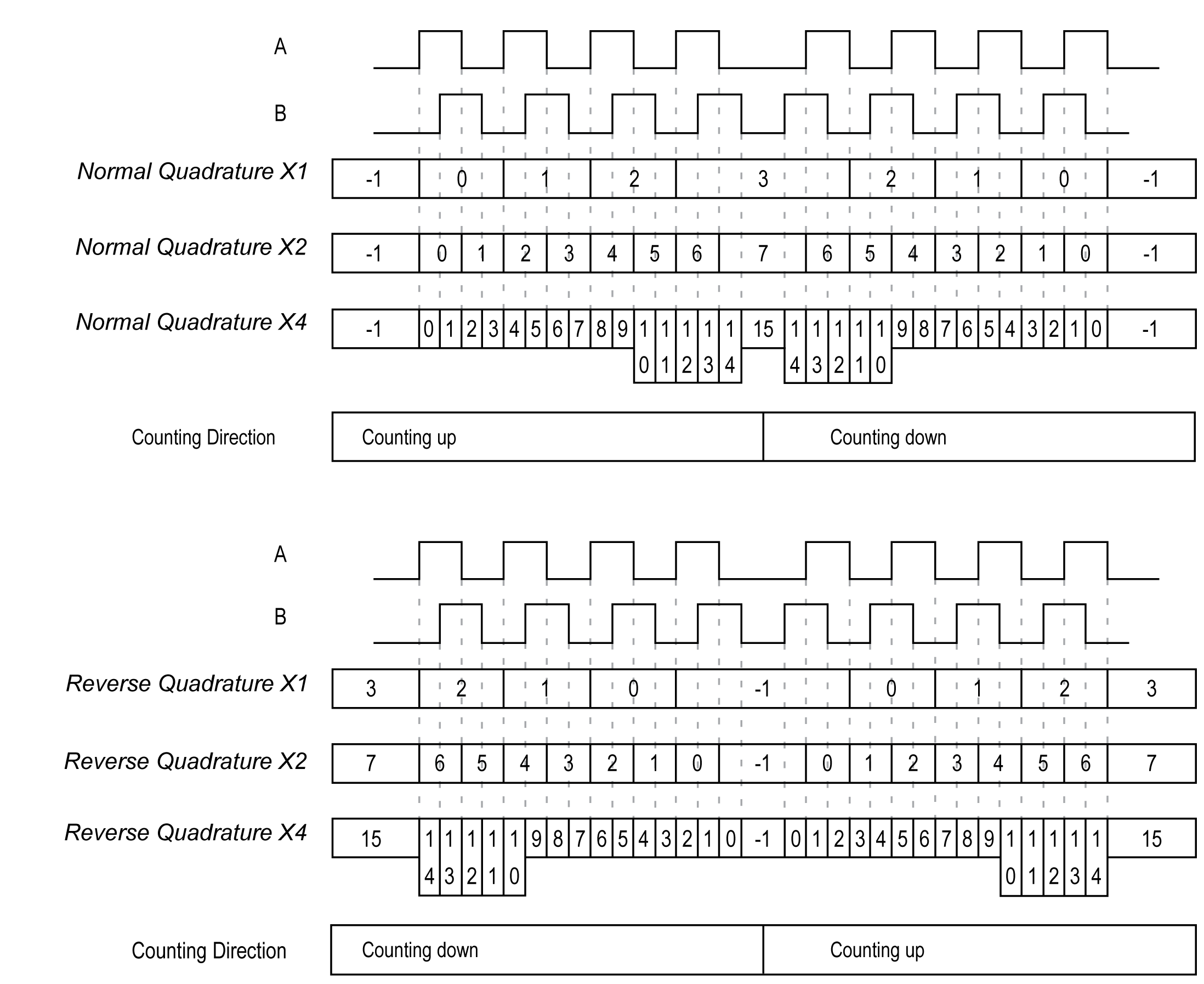
This table shows the 8 types of input modes available:
|
Input Mode |
Comment |
|---|---|
|
A = Up, B = Down |
default mode The counter increments on A and decrements on B. |
|
A = Pulse, B = Direction |
If there is a rising edge on A and B is true, then the counter decrements. If there is a rising edge on A and B is false, then the counter increments. |
|
Normal Quadrature X1 |
A physical encoder always provides 2 signals 90° shift that first allows the counter to count pulses and detect direction:
|
|
Normal Quadrature X2 |
|
|
Normal Quadrature X4 |
|
|
Reverse Quadrature X1 |
|
|
Reverse Quadrature X2 |
|
|
Reverse Quadrature X4 |
Up Down Principle Diagram
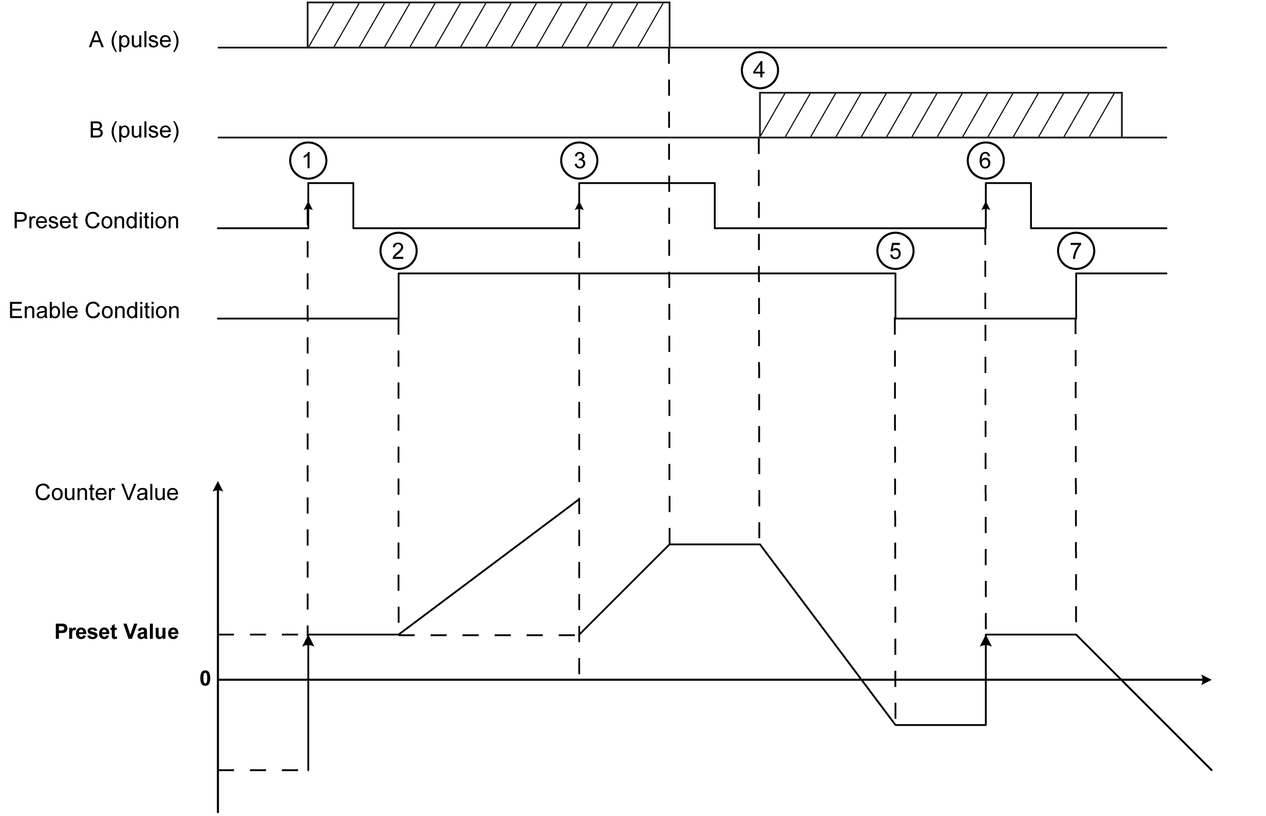
The figures shows the mode:

|
Stage |
Action |
|---|---|
|
1 |
On the rising edge of Preset condition, the current value is set to the preset value and the counter is activated. |
|
2 |
When Enable condition = 1, each pulse on A increment the counter value. |
|
3 |
On the rising edge of Preset condition, the current value is set to the preset value. |
|
4 |
When Enable condition = 1, each pulse on B decrements the counter value. |
|
5 |
When Enable condition = 0, the pulses on A or B are ignored. |
|
6 |
On the rising edge of Preset condition, the current value is set to the preset value. |
|
7 |
When Enable condition = 1, the pulses on B decrements the counter value. |
