Controller States Description
Introduction
This section provides a detailed description of the controller states.
| WARNING | |
|---|---|
(1) The controller states can be read in the PLC_R.i_wStatus system variable of the M241 PLCSystem library.
Controller States Table
The following table describes the controller states:
|
Controller State |
Description |
LED |
||
|---|---|---|---|---|
|
RUN (Green) |
ERR (Red) |
I/O (Red) |
||
|
BOOTING |
The controller executes the boot firmware and its own internal self-tests. It then checks the checksum of the firmware and user applications. |
OFF |
OFF |
ON |
|
OFF |
ON |
ON |
||
|
OFF |
ON |
OFF |
||
|
INVALID_OS |
There is not a valid firmware file present in the non-volatile memory. The controller does not execute the application. Refer to Firmware Management to restore a correct state. |
OFF |
Regular flash |
OFF |
|
EMPTY |
The controller has no application. |
OFF |
Single flash |
OFF |
|
EMPTY after a system error detected |
This state is the same as the other EMPTY state. However the application is present, and is intentionally not loaded. A reboot (power cycle), or a new application download, restores a correct state. |
OFF |
Fast flash |
OFF |
|
RUNNING |
The controller is executing a valid application. |
ON |
OFF |
OFF |
|
RUNNING with breakpoint |
This state is same as the RUNNING state with the following exceptions:
For more information on breakpoint management, refer to EcoStruxure Machine Expert Programming Guide. |
Single flash |
OFF |
OFF |
|
RUNNING with external error detected |
The controller is executing a valid application and a configuration, TM3, SD card, or other I/O error is detected. When I/O LED is ON, the details about the detected error can be found in PLC_R.i_lwSystemFault_1 and PLC_R.i_lwSystemFault_2. Any of the detected error conditions reported by these variables cause the I/O LED to be ON. |
ON |
OFF |
ON |
|
STOPPED |
The controller has a valid application that is stopped. See details of the STOPPED state for an explanation of the behavior of outputs and field buses in this state. |
Regular flash |
OFF |
OFF |
|
STOPPED with external error detected |
The controller is executing a valid application and a configuration, TM3, SD card, or other I/O error is detected. |
Regular flash |
OFF |
ON |
|
HALT |
The controller stops executing the application because it has detected an application error. |
Regular flash |
ON |
– |
|
Boot Application not saved |
The controller has an application in memory that differs from the application in non-volatile memory. At next power cycle, the application will be changed by the one from non-volatile memory. |
ON or regular flash |
Single flash |
OFF |
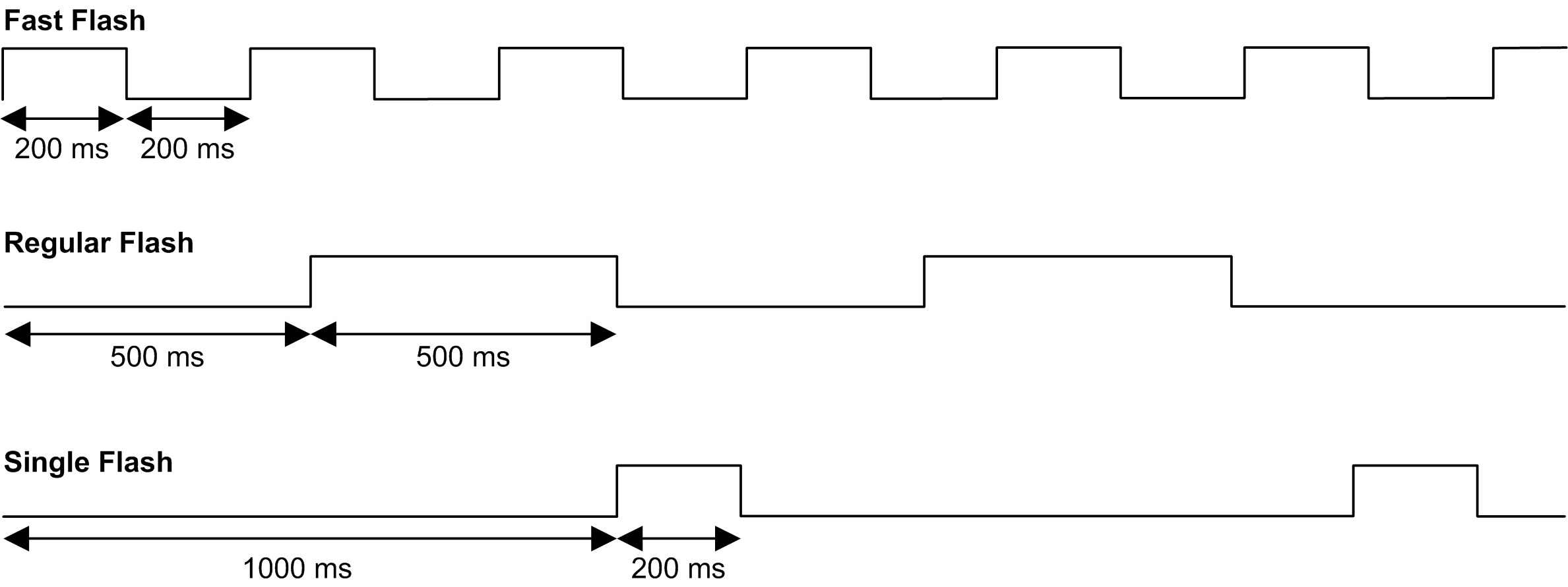
This timing diagram shows the difference between the fast flash, regular flash and single flash:

Details of the STOPPED State
The following statements are true for the STOPPED state:
-
The input configured as the Run/Stop input remains operational.
-
The output configured as the Alarm output remains operational and goes to a value of 0.
-
Ethernet, Serial (Modbus, ASCII, and so on), and USB communication services remain operational and commands written by these services can continue to affect the application, the controller state, and the memory variables.
-
All outputs initially assume their configured default state ( or ) or the state dictated by output forcing if used. For output used by a PTO function, the default value is ignored, in order not to generate an extra pulse. The subsequent state of the outputs depends on the value of the setting and on commands received from remote devices.
|
Task and I/O Behavior When Update IO While In Stop Is Selected |
When the Update IO while in stop setting is selected:
|
|
CAN Behavior When Update IO While In Stop Is Selected |
The following is true for the CAN buses when the setting is selected:
|
|
Task and I/O Behavior When Update IO While In Stop Is Not Selected |
When the setting is not selected, the controller sets the I/O to either the or condition (as adjusted for output forcing if used). After this, the following becomes true:
|
|
CAN Behavior When Update IO While In Stop Is Not Selected |
The following is true for the CAN buses when the setting is not selected:
|