PTO Configuration
Hardware Configuration
There are up to six inputs for a PTO channel:
-
Three physical inputs are associated to the PTO function through configuration and are taken into account immediately on a rising edge on the input:
-
REF input
-
INDEX input
-
PROBE input
-
-
Three inputs are associated with the MC_Power_PTO function block. They have no fixed assignment (they are freely assigned; that is, they are not configured in the configuration screen), and are read as any other input:
-
Drive ready input
-
Limit positive input
-
Limit negative input
-
| WARNING | |
|---|---|
There are up to three outputs for a PTO channel:
-
Either one physical output to manage pulse only, or two physical outputs to manage both pulse and direction; they must be enabled by configuration:
-
A / CW / Pulse
-
B / CCW / Direction
-
-
The other output,
DriveEnable, is used through the MC_Power_PTO function block.
Configuration Window Description
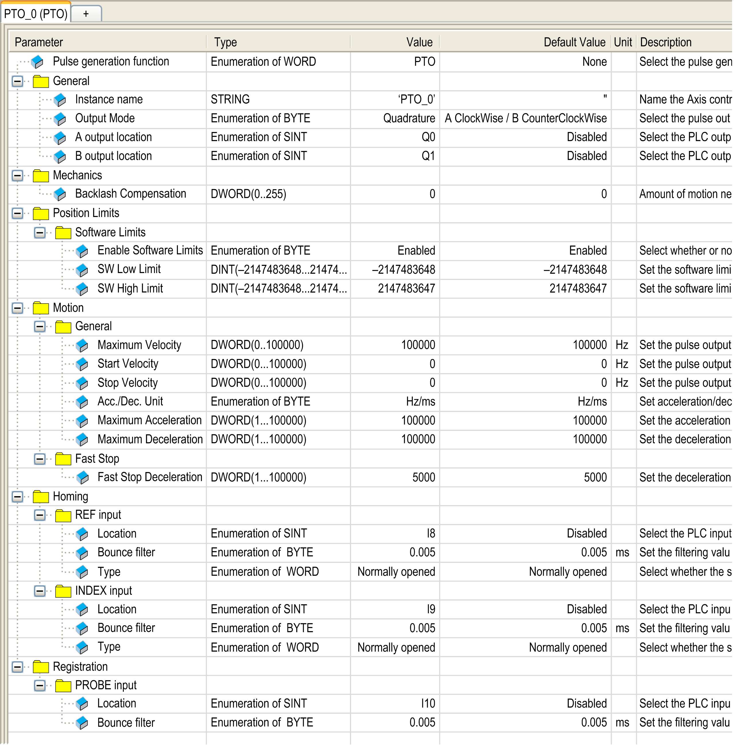
The figure provides an example of a configuration window on channel PTO_0:

The table describes each parameter available when the channel is configured in PTO mode:
|
Parameter |
Value |
Default |
Description |
|
|---|---|---|---|---|
|
General |
Instance name |
- |
PTO_0...PTO_3 |
Name of the axis controlled by this PTO channel. It is used as input of the PTO function blocks. |
|
A ClockWise / B CounterClockWise A Pulse / B Direction A Pulse Quadrature |
A ClockWise / B CounterClockWise |
Select the pulse output mode. |
||
|
A output location |
Disabled Q0...Q3 (fast outputs) Q4...Q7 (regular outputs)(1) |
Disabled |
Select the controller output used for the signal A. |
|
|
B output location |
Disabled Q0...Q3 (fast outputs) Q4...Q7 (regular outputs)(1) |
Disabled |
Select the controller output used for the signal B. |
|
|
Mechanics |
0...255 |
0 |
In quadrature mode, amount of motion needed to compensate the mechanical clearance when movement is reversed. |
|
|
Position Limits / Software Limits |
Enable Software Limits |
Enabled Disabled |
Enabled |
Select whether to use the software limits. |
|
SW Low Limit |
-2,147,483,648... 2,147,483,647 |
-2,147,483,648 |
Set the software limit position to be detected in the negative direction. |
|
|
SW High Limit |
-2,147,483,648... 2,147,483,647 |
2,147,483,647 |
Set the software limit position to be detected in the positive direction. |
|
|
Motion / General |
Maximum Velocity |
0...100000 (fast outputs) 0...1000 (regular outputs) |
100000 (fast outputs) 1000 (regular outputs) |
Set the pulse output maximum velocity (in Hz). |
|
Start Velocity...100000 (fast outputs) Start Velocity...1000 (regular outputs) |
0 |
Set the pulse output start velocity (in Hz). 0 if not used. |
||
|
0...100000 (fast outputs) 0...1,000 (regular outputs) |
0 |
Set the pulse output stop velocity (in Hz). 0 if not used. |
||
|
Hz/ms ms |
Hz/ms |
Set acceleration/deceleration as rates (Hz/ms) or as time constants from 0 to Maximum Velocity (ms). |
||
|
Maximum Acceleration |
1...100000 |
100000 |
Set the acceleration maximum value (in Acc./Dec. Unit). |
|
|
Maximum Deceleration |
1...100000 |
100000 |
Set the deceleration maximum value (in Acc./Dec. Unit). |
|
|
Motion / Fast Stop |
Fast Stop Deceleration |
1...100000 |
5000 |
Set the deceleration value in case an error is detected (in Acc./Dec. Unit) |
|
Homing / REF input |
Location |
Disabled I0...I7 (fast inputs) I8...I15 (regular inputs) |
Disabled |
Select the controller input used for the REF signal. |
|
Bounce filter |
0.000 0.001 0.002 0.005 0.010 0.05 0.1 0.5 1 5 |
0.005 |
Set the filtering value to reduce the bounce effect on the REF input (in ms). |
|
|
Type |
Normally opened Normally closed |
Normally opened |
Select whether the switch contact default state is open or closed. |
|
|
Homing / INDEX input |
Location |
Disabled I0...I7 (fast inputs) I8...I15 (regular inputs) |
Disabled |
Select the controller input used for the INDEX signal. |
|
Bounce filter |
0.000 0.001 0.002 0.005 0.010 0.05 0.1 0.5 1 5 |
0.005 |
Set the filtering value to reduce the bounce effect on the INDEX input (in ms). |
|
|
Type |
Normally opened Normally closed |
Normally opened |
Select whether the switch contact default state is open or closed. |
|
|
Registration / PROBE input |
Location |
Disabled I0...I7 (fast inputs) I8...I15 (regular inputs) |
Disabled |
Select the controller input used for the PROBE signal. |
|
Bounce filter |
0.000 0.001 0.002 0.005 0.010 0.05 0.1 0.5 1 5 |
0.005 |
Set the filtering value to reduce the bounce effect on the PROBE input (in ms). |
|
|
(1) Not available for M241 Logic Controller references with relay outputs. |
||||