Modbus Manager
Adding the Manager
To add a Modbus manager to your controller, select the in the , drag it to the , and drop it on one of the highlighted nodes.
For more information on adding a device to your project, refer to:
• Using the Hardware Catalog
• Using the Contextual Menu or Plus Button
Modbus Manager Configuration
To configure the Modbus Manager of your controller, double-click in the .
The Modbus Manager configuration window is displayed as below:
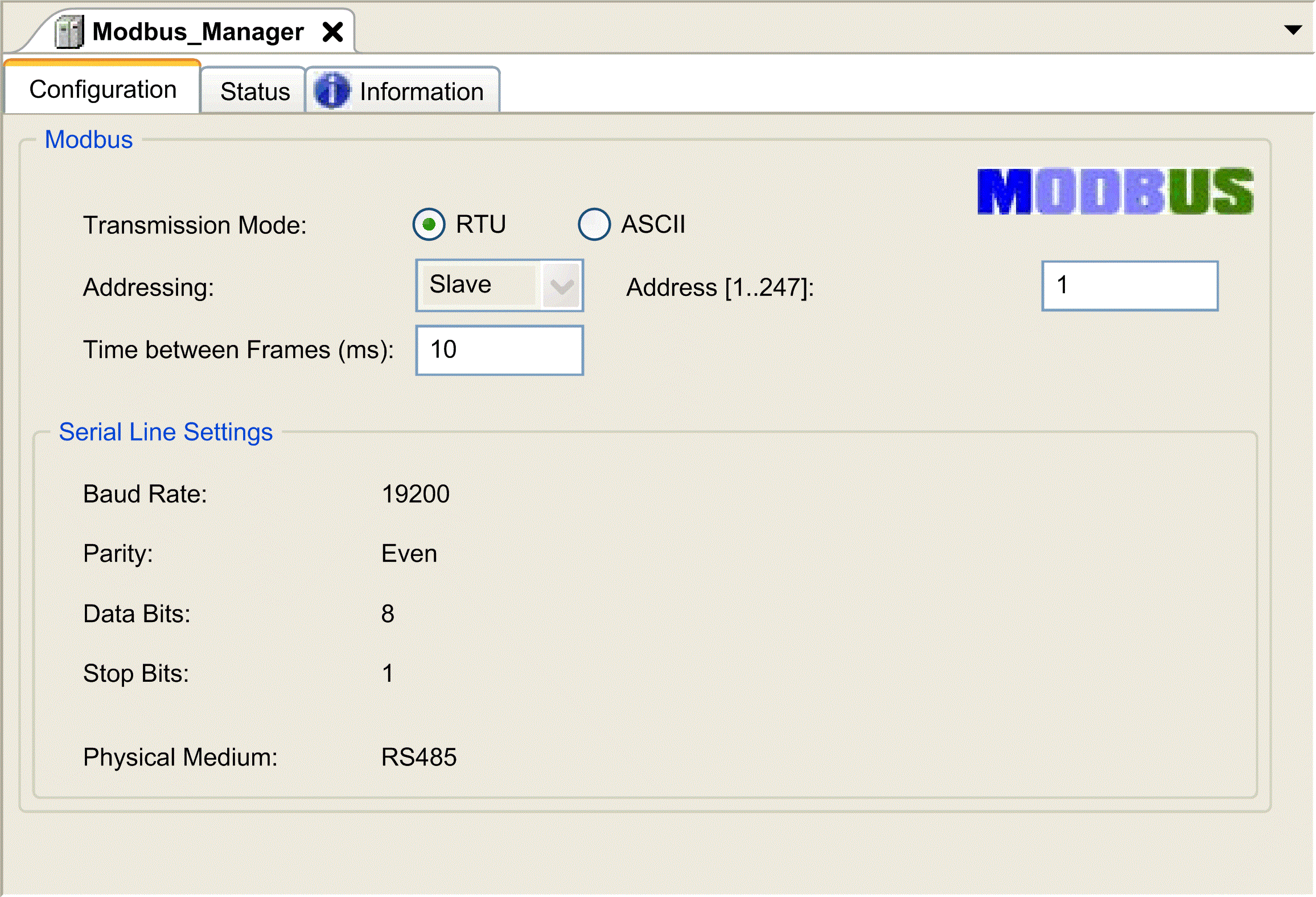
Set the parameters as described in this table:
|
Element |
Description |
|---|---|
|
|
Specify the transmission mode to use:
Set this parameter identical for each Modbus device on the link. |
|
|
Specify the device type:
|
|
|
Modbus address of the device, when slave is selected. |
|
|
Time to avoid bus-collision. Set this parameter identical for each Modbus device on the link. |
|
|
Parameters specified in the Serial Line configuration window. |
Modbus Master
When the controller is configured as a Modbus Master, the following function blocks are supported from the PLCCommunication Library:
-
ADDM
-
READ_VAR
-
SEND_RECV_MSG
-
SINGLE_WRITE
-
WRITE_READ_VAR
-
WRITE_VAR
For further information, see Function Block Descriptions of the PLCCommunication Library.
Modbus Slave
When the controller is configured as Modbus Slave, the following Modbus requests are supported:
|
Function Code Dec (Hex) |
Sub-Function Dec (Hex) |
Function |
|---|---|---|
|
1 (1 hex) |
– |
Read digital outputs (%Q) |
|
2 (2 hex) |
– |
Read digital inputs (%I) |
|
3 (3 hex) |
– |
Read multiple register (%MW) |
|
6 (6 hex) |
– |
Write single register (%MW) |
|
8 (8 hex) |
– |
Diagnostic |
|
15 (F hex) |
– |
Write multiple digital outputs (%Q) |
|
16 (10 hex) |
– |
Write multiple registers (%MW) |
|
23 (17 hex) |
– |
Read/write multiple registers (%MW) |
|
43 (2B hex) |
14 (E hex) |
Read device identification |
This table contains the sub-function codes supported by the diagnostic Modbus request 08:
|
Sub-Function Code |
Function |
|
|---|---|---|
|
Dec |
Hex |
|
|
10 |
0A |
Clears Counters and Diagnostic Register |
|
11 |
0B |
Returns Bus Message Count |
|
12 |
0C |
Returns Bus Communication Error Count |
|
13 |
0D |
Returns Bus Exception Error Count |
|
14 |
0E |
Returns Slave Message Count |
|
15 |
0F |
Returns Slave No Response Count |
|
16 |
10 |
Returns Slave NAK Count |
|
17 |
11 |
Returns Slave Busy Count |
|
18 |
12 |
Returns Bus Character Overrun Count |
This table lists the objects that can be read with a read device identification request (basic identification level):
|
Object ID |
Object Name |
Type |
Value |
|---|---|---|---|
|
00 hex |
Vendor name |
ASCII String |
Schneider Electric |
|
01 hex |
Product code |
ASCII String |
Controller reference |
|
02 hex |
Major / Minor revision |
ASCII String |
aa.bb.cc.dd (same as device descriptor) |
The following section describes the differences between the Modbus memory mapping of the controller and HMI Modbus mapping. If you do not program your application to recognize these differences in mapping, your controller and HMI will not communicate correctly. Thus it will be possible for incorrect values to be written to memory areas responsible for output operations.
| WARNING | |
|---|---|
When the controller and the Magelis HMI are connected via Modbus (HMI is master of Modbus requests), the data exchange uses simple word requests.
There is an overlap on simple words of the HMI memory while using double words but not for the controller memory (see following diagram). In order to have a match between the HMI memory area and the controller memory area, the ratio between double words of HMI memory and the double words of controller memory has to be 2.
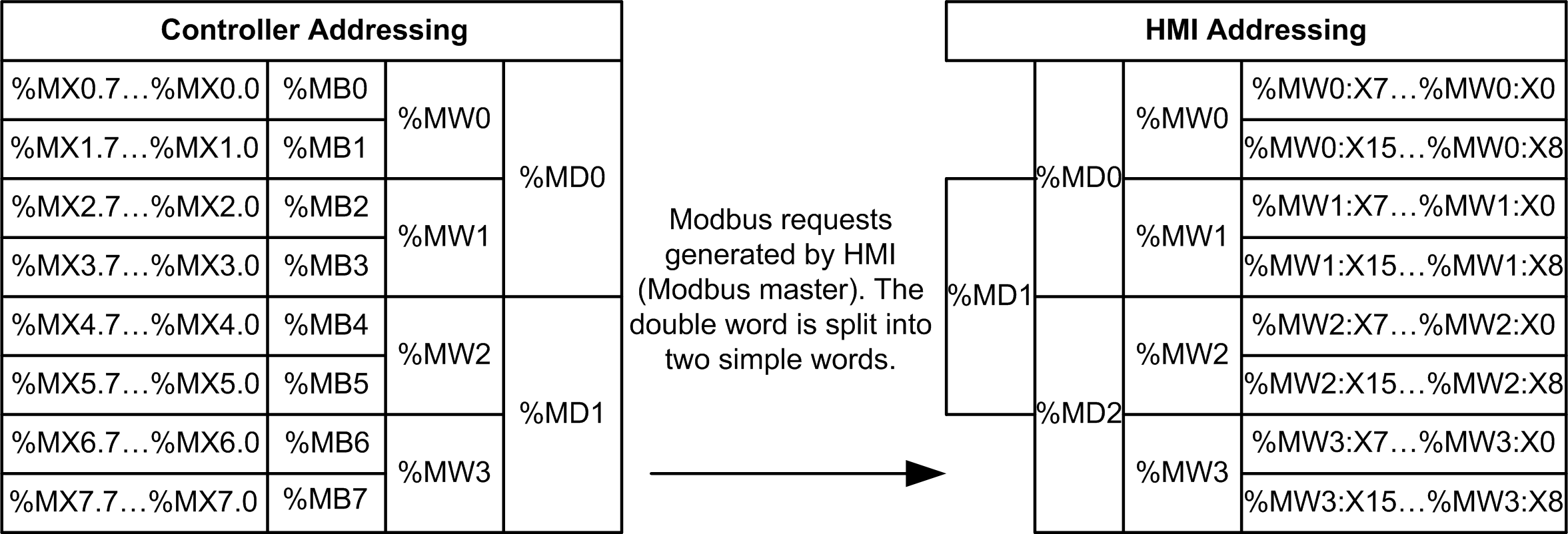
The following gives examples of memory match for the double words:
-
%MD2 memory area of the HMI corresponds to %MD1 memory area of the controller because the same simple words are used by the Modbus request.
-
%MD20 memory area of the HMI corresponds to %MD10 memory area of the controller because the same simple words are used by the Modbus request.
The following gives examples of memory match for the bits:
-
%MW0:X9 memory area of the HMI corresponds to %MX1.1 memory area of the controller because the simple words are split in 2 distinct bytes in the controller memory.