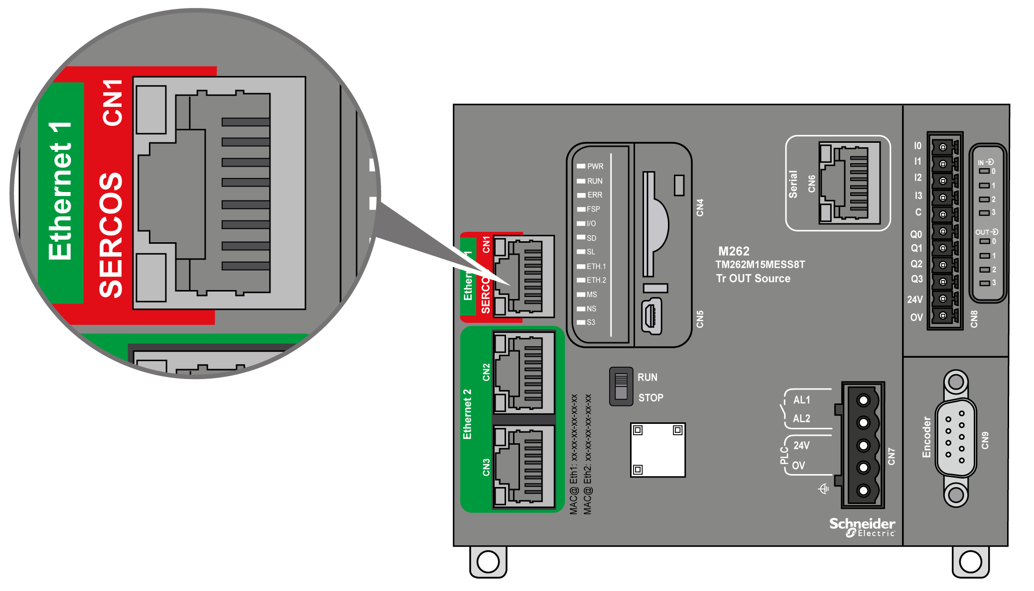
Wiring of the Commissioning PC
Connection of the commissioning PC:
|
Step
|
Action
|
|
1
|
Connect the Ethernet cable to the network adapter of your commissioning PC and to one of the Ethernet 2 ports of the Logic/Motion Controller. The ports are labeled with CN2 and CN3 on the device.
|
Wiring of the Sercos Bus
NOTE: The
Sercos bus can only be operated in a single-line architecture.
The wiring of the Sercos bus described in the present document relates to the sample project covered. The Sercos devices can alternatively be connected in a different order.
Connection of the Sercos devices:
|
Step
|
Action
|
|
1
|
Connect the Sercos cable to the Ethernet 1 port of the Logic/Motion Controller. The port is labeled SERCOS CN1 on the device.
|
|
2
|
At the SLC, connect this cable to any of the Sercos III RJ45 ports.
|
|
3
|
Continue the Sercos bus by connecting a second cable to the free Sercos III RJ45 port of the SLC, and connect it to any of the Sercos ports of the TM5NS31 bus coupler.
|
|
4
|
If required, continue the Sercos bus to the next TM5NS31 bus coupler or any other Sercos devices (drives, and so on) used.
|
The TM5NS31 bus coupler automatically detects the connected TM5/TM7 I/O devices and creates a corresponding local process image of the hardware configuration. Therefore, no further signal wiring is required.
