Slice Description
Overview
A slice is an expansion module that has one of the following functions in the TM5 System:
-
Expansion I/Os or
-
Power distribution or
-
Common distribution or
-
Expansion bus
The following figure shows the three components of a slice:

1 Bus base
2 Electronic module
3 Terminal block
| DANGER | |
|---|---|
The bus base and the terminal block for the electronic module, must be ordered separately. For the references see respective sections below.
When assembled the three components form an integral unit that resists vibration and electrostatic discharge.
| NOTICE | |
|---|---|
The compatibility table gives the possible associations between components of a slice.
Bus Base Description
The following figures shows the different parts of the bus base:

1 Locking lever
2 DIN rail locking mechanism
3 DIN rail contact
4 Guides for assembly of the electronic module
5 Rotation axle for terminal block
6 TM5 bus power contacts
7 TM5 bus data contacts
8 24 Vdc I/O power segment contacts
9 Interlocking guides
10 Address setting rotary switches (optional, depending on references)
This table gives the different types of bus bases:
|
Reference |
Bus Base Description |
Color |
|---|---|---|
|
TM5ACBM11 |
Bus base 24 Vdc 24 Vdc I/O power segment pass-through |
White |
|
TM5ACBM15 |
Bus base 24 Vdc 24 Vdc I/O power segment pass-through with address setting |
White |
|
TM5ACBM01R |
Bus base 24 Vdc for PDM and Receiver modules 24 Vdc I/O power segment left isolated |
Gray |
|
TM5ACBM05R |
Bus base 24 Vdc for PDM and Receiver modules 24 Vdc I/O power segment left isolated with address setting |
Gray |
|
TM5ACBM12 |
Bus base for AC modules 24 Vdc I/O power segment pass-through |
Black |
Electronic Module Description
The following figure shows the different parts of the electronic modules:

1 Locking lever
2 Guides for assembly
3 Display (LEDs)
4 Slot for labeling
5 Slot to code the electronic module and the associated terminal block
6 Internal fuse exchangeable (depending on references)
This table presents the different types of electronic modules:
|
Reference |
Electronic Module Description |
Color |
Refer to |
|---|---|---|---|
|
TM5SD•• |
Digital modules |
White or black |
|
|
TM5SA•• |
Analog modules |
White |
|
|
TM5SPS1• |
Power Distribution Modules (PDM) |
Gray |
|
|
TM5SPS2• |
|||
|
TM5SPS3 |
Interface Power Distribution Module (IPDM) |
Gray |
|
|
TM5SE•• |
Expert modules |
White |
Modicon TM5 Expert (High Speed Counter) Modules Hardware Guide |
|
TM5SBET•• |
Transmitter modules |
White |
|
|
TM5SBER•• |
Receiver module |
Gray |
|
|
TM5SPD•• |
Common Distribution Modules (CDM) |
White |
|
|
TM5SD000 |
Dummy module |
White |
Terminal Block Description
The main features of the terminal block are:
-
Tool-free wiring with spring clamp push-in technology
-
Push-button wire release
-
Ability to label each terminal
-
Plain text labeling also possible
-
Test access for standard probes
-
Can be custom-coded
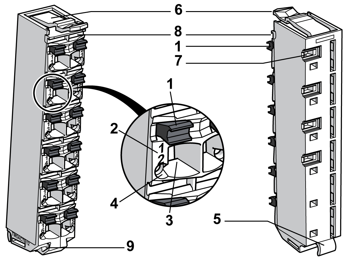
The following figure shows the different parts of the terminal block:

1 Wire release push-button
2 Pin assignment
3 Spring clamp connector
4 Test access point
5 Hinge for the axle on the bus base
6 Latch for the electronic module
7 Back slot for coding
8 Front slot for labeling
9 Slot for cable tie
This table gives the different types of terminal blocks:
|
Reference |
Terminal Block Description |
Color |
|---|---|---|
|
TM5ACTB06 |
24 Vdc, 6-pin terminal block |
White |
|
TM5ACTB12 |
24 Vdc, 12-pin terminal block |
White |
|
TM5ACTB12PS |
24 Vdc, 12-pin terminal block for PDM, IPDM and Receiver electronic module |
Gray |
|
TM5ACTB16 |
24 Vdc, 16-pin terminal block |
White |
|
TM5ACTB32 |
240 Vac, 12-pin terminal block |
Black |