Web Server
Introduction
The TM3 bus coupler supports a Web server, offering access to information such as configuration data, module status, I/O data, network statistics, and diagnostic information.
In addition the Web server allows you to monitor this information, the bus coupler network and I/O remotely.
You can access the Web server with HTTPS (secured connections). HTTP (non secured connections) is not supported.
The Web server is accessible through the bus coupler USB port and Ethernet port by specifying the IP address or hostname in the address bar. You can use the pages of the Web server for network setup and control the I/O module outputs as well as application diagnostics and monitoring.
Use a PC providing a USB port and/or an Ethernet interface to connect to the Web server by using a Web browser.
The Web server can be accessed by the web browsers listed below:
-
Google Chrome (version ≥ 71)
-
Mozilla Firefox (version ≥ 64)
-
Microsoft Edge (version ≥ 42)
The Web server allows you to monitor a bus coupler remotely, to perform various maintenance activities including modifications to output modules data and network configuration parameters. Care must be taken to ensure that the immediate physical environment of the machine and process is in a state that will not present safety risks to people or property before exercising control remotely.
| WARNING | |
|---|---|
Web Server Access
You can manage the user accounts on the Web server on MAINTENANCE / User Accounts.
By default, the user name is Administrator, and the password is Administrator. You must change the password at the first login.
| WARNING | |
|---|---|
Resetting the Password
To reset the password:
|
Step |
Action |
|---|---|
|
1 |
Connect to the bus coupler using the USB port. Ensure the Ethernet cable is disconnected. |
|
2 |
Open the browser. |
|
3 |
Enter the IP address 90.0.0.1. |
|
4 |
Move the position of any rotary switch to any other position. Result: MS LED is flashing red. The button is displayed. |
|
5 |
Click . |
|
6 |
Move the position of the changed rotary switch to its previous position. Result: The button is no longer displayed. |
Page
The login page is the entry point to get authenticated by the Web server. The certificate must be validated. To access the website login page shown in the following illustration, type in your navigator the IP address of the TM3 bus coupler or IP address 90.0.0.1 if you are connected by USB. To login to the Web server, enter the user name and password and click .

The Web server contains the following pages:
Page
The page shows the product details of TM3 bus coupler.
The section of page consists of:
|
Element |
Description |
|---|---|
|
|
|
|
|
Vendor ID of the bus coupler |
|
|
Vendor name of the bus coupler |
|
|
Product ID of the bus coupler |
|
|
Product name of the bus coupler |
|
|
Product reference of the bus coupler |
|
|
Serial number of the bus coupler |
|
|
Click the button to locate the bus coupler. The LEDs of the bus coupler flash red for few seconds. |

/
The sub-page displays the status of the bus coupler and details about identification:
|
Element |
Description |
|---|---|
|
|
|
|
|
Displays the cause of the last stop of the bus coupler. |
|
|
Displays whether a USB cable is connected to the bus coupler. |
|
|
Displays one of the following operating modes of the bus coupler: |
|
|
Displays one of the following configuration status of the bus coupler: |
/
The sub-page displays the configuration and status of Ethernet connection:
|
Element |
Description |
|---|---|
|
|
|
|
|
MAC address of the bus coupler. |
|
|
Displays the IP mode of the bus coupler:
|
|
|
IP address of the bus coupler |
|
|
Subnet mask of the bus coupler |
|
|
Gateway address of the bus coupler |
|
|
Resets all the counter values to zero. |
|
|
Refreshes the values. |
|
|
|
|
|
Displays the number of the bytes transmitted. |
|
|
Displays the number of frames transmitted. |
|
|
Displays the number of the frames transmitted in error. |
|
|
Displays the number of the bytes received. |
|
|
Displays the number of frames received. |
|
|
Displays the number of the frames received in error. |
|
|
Resets all the counter values to zero. |
|
|
Refreshes the values. |
|
|
|
|
|
Displays one of the following status of the bus coupler: |
|
|
Made from the and the MAC address. |
|
|
Read only. The is defined in MAINTENANCE / Ethernet. |
|
|
Displays one of the following states of the CN1 port: |
|
|
Displays one of the following roles of the CN1 port: |
|
|
Displays one of the following states of the CN2 port: |
|
|
Displays one of the following roles of the CN2 port: |
|
|
Refreshes the values. |

/
The sub-page displays the status information of EtherNet/IP:
|
Element |
Description |
|---|---|
|
|
Resets all the counter values to zero. |
|
|
Refreshes the values. |
|
|
|
|
|
Displays the number of I/O messages transmitted through EtherNet/IP. |
|
|
Displays the number of I/O messages received through EtherNet/IP. |
|
|
Displays the number of erroneous I/O messages that were not transmitted through EtherNet/IP. |
|
|
Displays the number of erroneous I/O messages that were not received through EtherNet/IP. |
|
|
Displays the number of UCMM requests. |
The sub-page displays the status information of Modbus TCP:
|
Element |
Description |
|---|---|
|
|
Resets all the counter values to zero. |
|
|
Refreshes the values. |
|
|
|
|
|
Displays the number of Modbus messages transmitted through Modbus TCP. |
|
|
Displays the number of Modbus messages received through Modbus TCP. |
|
|
Displays the number of Modbus detected error messages transmitted through Modbus TCP. |
The page displays the I/O modules configuration imported from the TM3 Bus Coupler IO Configurator. The configuration file is an .SPF format.
|
Element |
Description |
|---|---|
|
toolbar |
|
|
|
Read only button. |
|
|
Allows you to import the I/O modules configuration files generated by the TM3 Bus Coupler IO Configurator. Click to import the files. |
|
|
Read only button. |
|
toolbar |
|
|
|
Allows you to apply the I/O modules configuration files on the TM3 bus coupler. If the configuration mismatch the hardware, an error message is generated. |
|
toolbar |
Read only toolbar. |
Page
The page displays the TM2 and TM3 expansion modules that are connected to the TM3 bus coupler.
page without detected modules:
page with modules and details:
1 Bus Monitoring
2 Selected module
3 Reconcile button
4 Module details
The page shows and describes all the modules detected by the bus coupler and allows you to:
-
See the state of a selected module (running or not running) and the protocol used.
-
Read the value of an input or output.
-
Force a value to an output by clicking .
-
Identify a module by clicking .
|
Element |
Description |
|---|---|
|
|
Allows you to detect the modules connected to the bus coupler. |
|
|
Reserves the bus to allow you to force the module outputs. You can click the button when the bus coupler is configured and not controlled by a controller (EtherNet/IP or Modbus TCP)(1). Result: You are notified that the I/O bus is controlled by the Web interface. You can edit the output values. Click to release the control of the I/O bus. |
|
(1) When connected on EtherNet/IP, the I/O bus is controlled, no matter the controller state. When connected on Modbus TCP, the I/O bus is not controlled when the controller is in |
|
Module Details
The module details view provides the following data:
-
Module name and description
-
Module state
-
A list of its I/Os
This list of I/Os allows you to view a real-time value of an input and to write the value of an output.
The view has buttons to modify the format of the displayed values.
Output Forcing
-
When is enabled, click a module to force its outputs.
-
Set the output values you wish to force for the module in the column of the list of its I/Os.
-
Click the button.
Result: A message is displayed.
-
Click to validate the modifications and send them to the bus coupler.
Click to cancel the modifications.
As the modules are not identified automatically, click the button to identify the modules.
Page
The page allows you to view and edit the configuration of the bus coupler.
The page contains the following sub-pages:
/
The sub-page allows you to enter your login password to access the Web server:
|
Element |
Description |
|---|---|
|
|
|
|
|
List of the following user accounts:
NOTE: Depending on your account, you have access to some web pages. See the table below for the accessible web pages.
|
|
|
Selected if the account is enabled. |
|
|
|
|
|
Enter the current password of the user account. |
|
|
Enter a password for the user account.
NOTE: Minimum ten characters, maximum 32 characters and use a...z, A...Z, 0...9 alphanumeric characters. To reset the password, refer to Resetting the Password.
|
|
|
Enter the password again of the selected account. |
|
|
Saves your new password. |
This table describes the accessible pages depending on the user account:
|
Web pages |
Sub pages |
|
|
|
|---|---|---|---|---|
|
|
– |
✓ |
✓ |
✓ |
|
|
– |
✓ |
✓ |
– |
|
|
|
✓ |
✓ |
✓ |
|
|
✓ |
✓ |
✓ |
|
|
|
✓ |
✓ |
✓ |
|
|
|
✓ |
✓ |
✓ |
|
|
|
– |
✓ |
– |
– |
|
|
|
✓ |
– |
– |
|
|
✓ |
– |
– |
|
|
|
✓ |
✓(1) |
✓(1) |
|
|
|
✓ |
– |
– |
|
|
- |
✓ |
✓ |
– |
|
|
– |
||||
|
|
✓ |
– |
– |
|
|
(1) You can only modify your user account. |
||||
The sub-page allows you to define a message which is displayed to users at log-in:
|
Element |
Description |
|---|---|
|
|
|
|
|
When selected, you can define a message that is displayed at log-in. |
|
|
Displays the message defined. |
|
|
Reset to default message. |
|
|
Applies your changes. |
/
The following illustration shows the sub-page:
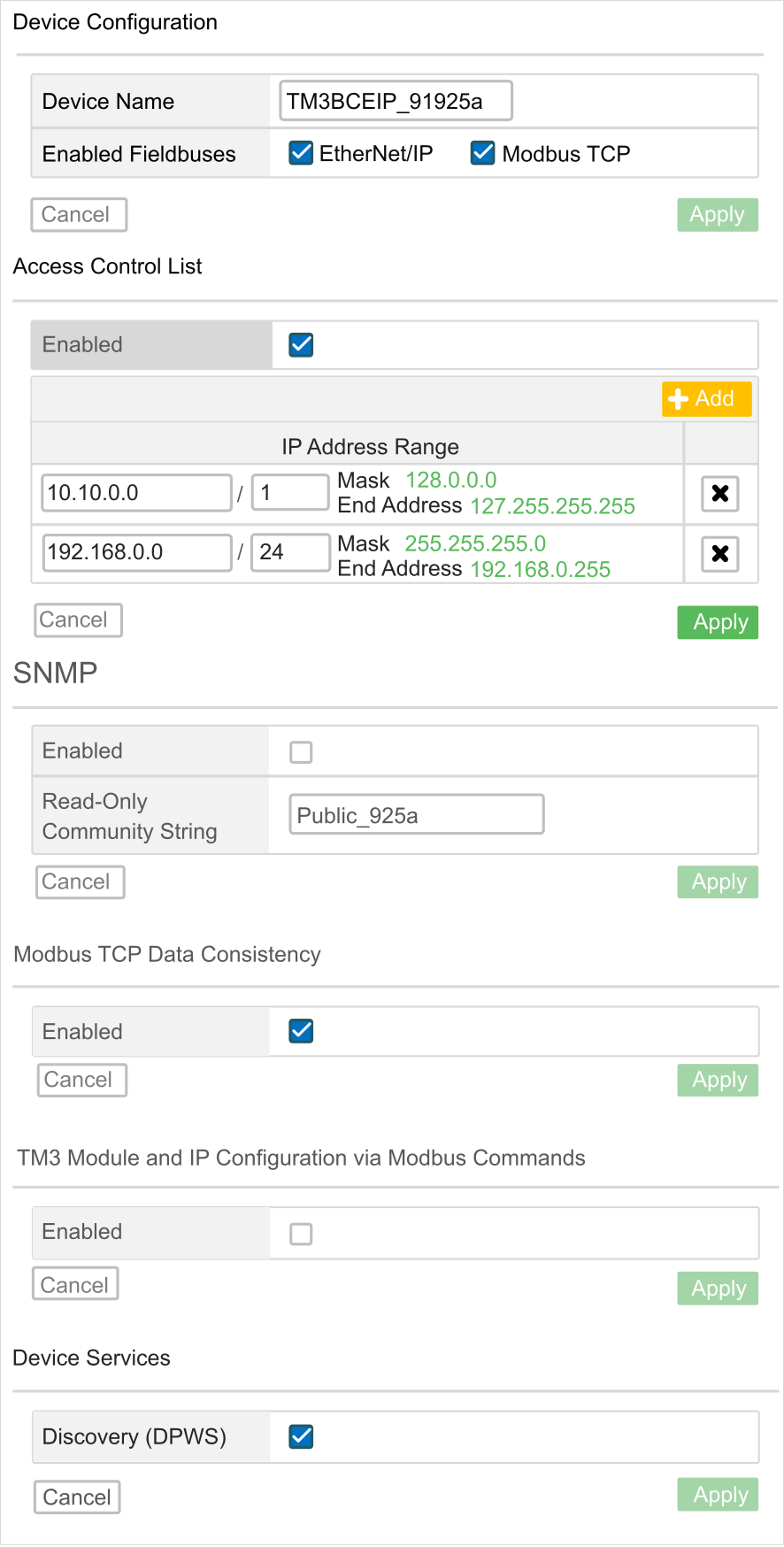
The sub-page allows you to change the configuration settings of the bus coupler:
|
Page |
Description |
|---|---|
|
|
|
|
|
Name of the bus coupler used in DHCP mode. If you modified the , do a power cycle of the bus coupler to take it into account. |
|
|
Allows you to select the communication types: |
|
|
Cancels the configuration settings. |
|
(1) |
Saves the configuration settings. |
|
|
|
|
|
Enables or disables the ACL management. Enable it to configure the IP address ranges allowed to communicate with the bus coupler. |
|
|
Adds a line of IP address range. |
|
|
Shows the ranges of IP addresses. Each line corresponds to an IP address range allowed to communicate with the bus coupler. The first field represents the starting IP address. The second one is the number of free bits. The maximum number of ranges is 10. |
|
|
Cancels the configuration settings. |
|
(1) |
Saves the configuration settings. |
|
|
|
|
|
Enables or disables the SNMP management. Disabled by default. |
|
|
Shows the community name. Allows you to change the community name. The maximum number of characters is 16. |
|
|
Cancels the configuration settings. |
|
(1) |
Saves the configuration settings. |
|
|
|
|
|
Allows an internal copy of the input data registers (3000-3499 or 13000-13499) to be kept since the first read request is received until the second read request is received OR until the monitoring timeout is elapsed. Is enabled by default when the I/O modules configuration need more than 124 words to read the data of the input. |
|
|
Cancels the configuration settings. |
|
(1) |
Saves the configuration settings. |
|
|
|
|
|
Allows controller to send TM3 configuration through Modbus requests. |
|
|
Cancels the configuration settings. |
|
(1) |
Saves the configuration settings. |
|
|
|
|
|
Allows the bus coupler to be located in the LAN using IPv6 or IPv4. Enabled by default. |
|
|
Cancels the configuration settings. |
|
(1) |
Saves the configuration settings. |
|
(1) Modifying the Setup configuration requires a power cycle of the bus coupler to apply the configuration settings. |
|
/
The sub-page allows you to change the network settings:
|
Element |
Description |
|---|---|
|
|
|
|
|
Allows you to select the following operating modes of the bus coupler: |
|
|
IP address of the bus coupler. For more information, refer to TM3 Bus Coupler - Hardware Guide. |
|
|
Subnet mask of the bus coupler. |
|
|
Gateway address of the bus coupler. |
|
(1) |
Saves the configuration settings. |
|
|
Cancels the configuration settings. |
|
|
|
|
|
Allows you to enter the target IP address to check if the bus coupler can reach the device on the network. |
|
|
Sends a message to the IP address. |
|
|
|
|
|
Enables or disables the RSTP configuration. |
|
|
Configure the switch priority to be chosen as the root switch. A low number represents a high priority. |
|
|
Read only tab. Interval between the generation of spanning-tree configuration messages by the root switch. These messages mean that the switch is operational. |
|
|
Read only tab. The number of seconds a switch waits without receiving spanning-tree configuration messages before attempting a configuration. |
|
|
Read only tab. The number of seconds the port waits before changing from its spanning-tree learning and listening states to the forwarding state. |
|
(1) Modifying the Ethernet configuration requires a power cycle of the bus coupler to apply the configuration settings. |
|
/
The sub-page shows the firmware version of the TM3 bus coupler and allows you to update its firmware:
|
Element |
Description |
|---|---|
|
|
|
|
|
Firmware version |
|
|
Web server version |
|
|
|
|
|
Allows you to select the new firmware file for the bus coupler. |
|
|
Allows you to apply the new firmware. |
To update the bus coupler firmware:
|
Step |
Action |
|---|---|
|
1 |
Log into the Web server. Refer to the instructions provided by the Web server Login Page. |
|
2 |
Verify in the page that the bus coupler is not exchanging data with the controller. |
|
3 |
Click . |
|
4 |
Click , then select the firmware file. Result: The following information is displayed: 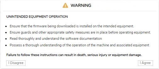
|
|
5 |
Read the information carefully and, if you agree, click . Result: At the end of the download and verification of the file, a confirmation window is displayed. |
|
6 |
Click to close the confirmation window, then click . Result: At the end of the firmware update, a message is displayed to inform you whether the firmware update is completed successfully. |
/
The sub-page shows the firmware version of the modules configured and allows you to update its firmware:
|
Element |
Description |
|---|---|
|
|
|
|
|
Slot number of the module |
|
|
Reference of the module |
|
|
Firmware version of the module |
|
|
|
|
|
Allows you to select the new firmware file for the module.
NOTE: You can select only a single firmware file. All modules on the bus corresponding to the selected firmware are updated.
|
|
|
Allows you to apply the new firmware. |
To update the module firmware:
|
Step |
Action |
|
|---|---|---|
|
1 |
Log into the Web server. Refer to the instructions provided by the Web server Login Page. |
|
|
2 |
Verify in the page that the bus coupler is not exchanging data with the controller. |
|
|
3 |
Click . |
|
|
4 |
Click , then select the firmware file. Result: The firmware file is selected. |
|
|
5 |
Click . Result: The following information is displayed:
|
|
|
6 |
Read the information carefully and, if you agree, click . Result: A restart window is displayed. |
|
|
7 |
Click to proceed. Result: The file is verified and downloaded. The TM3 bus coupler reboots and a confirmation message is displayed. |
|
|
8 |
After the confirmation message is displayed, remove power from the bus coupler (and TM3XREC1 receiver module, if any). |
|
|
9 |
Restore power to the bus coupler (and TM3XREC1 receiver module, if any). Result: The module firmware is updated. |
|
/
The sub-page lists the log files. Some of the information in the log files comes from internal interactions of the firmware and is intended to be used by Schneider Electric Technical Support:
|
Element |
Description |
|---|---|
|
|
|
|
|
Shows the list of the log files. |
|
|
Displays the size of the log files. |
|
|
Allows you to download the log files. |
|
|
|
|
|
Enable or disable the SysLog Client. Disabled by default. |
|
|
Read-only tab. TCP port number for . |
|
|
Allows you to set the SysLog Server IP Address. |
|
|
Cancels the configuration settings. |
|
|
Saves the configuration settings. |
|
|
|
|
|
Allows you to send a test message stored under the folder /usr/Syslog. |
/
FDR mode activation:
The service allows you to replace an inoperable device by a new one without the need to configure it.
|
Mode |
Rotary switches position |
|
|---|---|---|
|
FDR mode enabled |
TENS: 09 to 15 |
ONES: 0 to 9 |
|
Element |
Description |
|---|---|
|
|
|
|
|
Name of the bus coupler. Syntax is TM3BCEIP_+XXY (XX represents TENS switch position and Y represents ONES rotary switch position).
NOTE: If the bus coupler is in mode, the name might not respect this syntax.
|
|
|
|
|
|
|
|
|
|
|
|
Allows you to enable or disable the automatic backup. When the TM3BCEIP is selected, it sends the .prm file to the FDR server, respecting the timing configured in the automatic backup period. |
|
|
Allows you to set the backup period . Default value for the backup period is 1800 seconds. |
|
|
When is enabled and is unchecked
When is enabled and is checked with a of 600 seconds:
|
|
|
Cancels any changes made to the values. |
|
|
Saves the values to the Flash memory. |
|
|
|
|
|
|
|
|
|
|
|
Allows you to manually restore (by downloading) the device parameters file from the FDR server to the bus coupler and to apply the configuration received without restarting. This button cannot be clicked when the bus coupler is controlled by the controller or by the Web. |
|
|
|
|
|
|
|
|
|
|
|
Allows you to manually backup (by uploading) the device parameters file from the bus coupler to the FDR server. |