Grounding the TM3 Digital I/O Modules
Overview
Due to the effects of electromagnetic interference, cables carrying fast I/O, analog I/O, and the fieldbus communication signals must be shielded.
| WARNING | |
|---|---|
1Multipoint grounding is permissible if connections are made to an equipotential ground plane dimensioned to help avoid cable shield damage in the event of power system short-circuit currents.
The use of shielded cables requires compliance with the following wiring rules:
-
For protective earth ground connections (PE), metal conduit or ducting can be used for part of the shielding length, provided there is no break in the continuity of the ground connections. For functional earth ground (FE), the shielding is intended to attenuate electromagnetic interference and the shielding must be continuous for the length of the cable. If the purpose is both functional and protective, as is often the case for communication cables, the cable must have continuous shielding.
-
Wherever possible, keep cables carrying one type of signal separate from the cables carrying other types of signals or power.
Shielded Cables Connections
Cables carrying fast I/O, analog I/O, and the fieldbus communication signals must be shielded. The shielding must be securely connected to ground. Fast I/O and analog I/O shields may be connected either to the functional earth ground (FE) or to the protective earth ground (PE) of your TM3 expansion module. The fieldbus communication cable shields must be connected to the protective earth ground (PE) with a connecting clamp secured to the conductive backplane of your installation.
Protective Earth Ground (PE) on the Backplane
The protective earth ground (PE) is connected to the conductive backplane by a heavy-duty wire, usually a braided copper cable with the maximum allowable cable section.
Functional Earth Ground (FE) on the DIN Rail
The DIN Rail for your TM3 system is common with the functional earth ground (FE) plane and must be mounted on a conductive backplane.
| WARNING | |
|---|---|
Functional Earth Ground (FE) Connections
To connect the functional earth ground (FE):
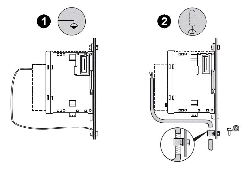
|
Label |
Signification |
Description |
|---|---|---|
|
1 |
Grounding of the module |
Connect the module to the functional earth ground (FE) terminal. |
|
2 |
Grounding of the sensor |
Attach and ground the shielding of cables as close as possible to the controller:
The shielding must be clamped tightly enough to the metal support to achieve good contact. |