Physical Description
Introduction
This section describes the physical characteristics of the TM3 transmitter and receiver modules.
TM3 Transmitter Modules
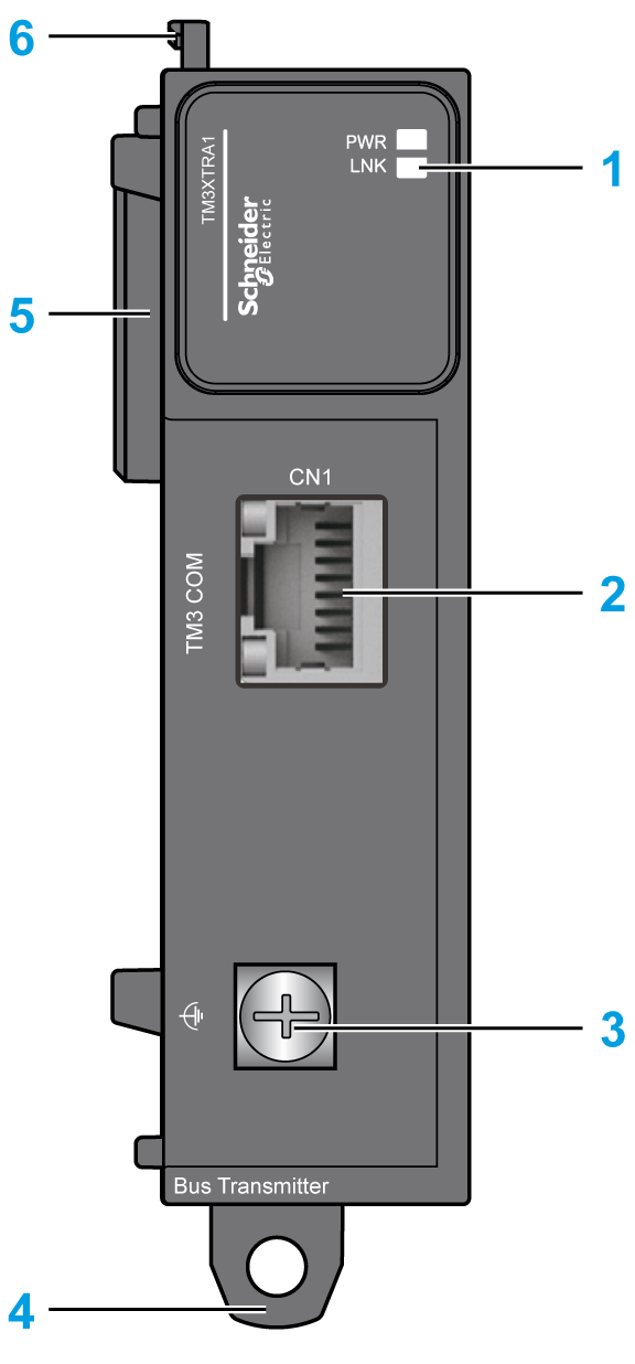
The following figure shows the parts of the TM3XTRA1 transmitter expansion module:

This table describes the main elements of the TM3XTRA1 transmitter expansion module shown above:
|
N° |
Description |
Refer to |
|---|---|---|
|
1 |
LEDs for displaying the link activity and power supply status |
– |
|
2 |
TM3 bus port |
– |
|
3 |
Screw for functional ground connection |
|
|
4 |
Clip-on lock for 35 mm (1.38 in.) DIN rail |
|
|
5 |
Expansion connector for TM3 I/O bus (left side only) |
– |
|
6 |
Locking device for attachment to the previous module |
– |
TM3 Receiver Modules
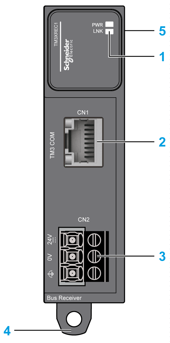
The following figure shows the parts of the TM3XREC1 receiver expansion module:

This table describes the main elements of the TM3XREC1 receiver expansion module shown above:
|
N° |
Description |
Refer to |
|---|---|---|
|
1 |
LEDs for displaying the link activity and power supply status |
– |
|
2 |
TM3 bus port |
– |
|
3 |
Power supply screw terminal block |
|
|
4 |
Clip-on lock for 35 mm (1.38 in.) DIN-rail |
|
|
5 |
Expansion connector for TM3 I/O bus (right side only) |
– |