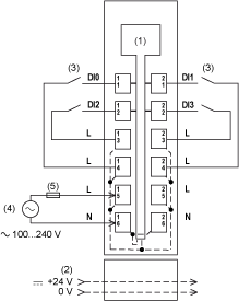
Wiring Diagram
The following illustration shows the wiring diagram for TM5SDI4A:

1 Internal electronics
2 24 Vdc I/O power segment integrated into the bus bases
3 2-wire sensor
4 External power supply: 100...240 Vac
5 External fuse type T slow-blow 1 A - 250 V
|
WARNING
|
|
UNINTENDED EQUIPMENT OPERATION
Do not connect wires to unused terminals and/or terminals indicated as “No Connection (N.C.)”.
Failure to follow these instructions can result in death, serious injury, or equipment damage.
|
|
WARNING
|
|
UNINTENDED EQUIPMENT OPERATION
Use the sensor and actuator power supply only for supplying power to sensors or actuators connected to the module.
Failure to follow these instructions can result in death, serious injury, or equipment damage.
|