TM5SDO12T Wiring Diagram
Wiring Diagram
The following illustration shows the wiring diagram for the TM5SDO12T:
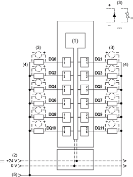
1 Internal electronics
2 24 Vdc I/O power segment integrated into the bus bases
3 Inductive load protection
4 2-wire load
5 0 Vdc I/O power segment by external connection
NOTE: I/O electronic modules and the field devices connected to them must all reside on the same 24 Vdc I/O power segment. If not, the status LEDs may not function correctly. In addition, there may potentially be more significant consequences such as an explosion and/or fire hazard.
| WARNING | |
|---|---|
The 12-output TM5SDO12T electronic module can independently support 1-wire devices. To connect 2-wire devices, you can add a TM5SPDG12F Common Distribution module.
The following illustration shows the wiring diagram for the TM5SPDG12F and TM5SDO12T:
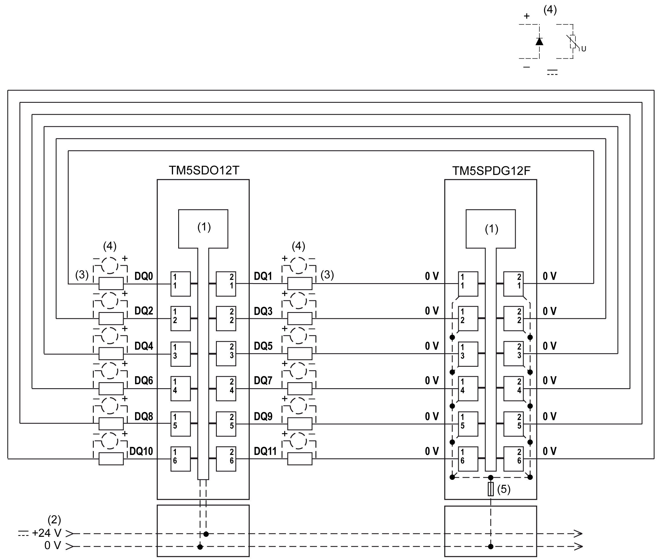
1 Internal electronics
2 24 Vdc I/O power segment integrated into the bus bases
3 2-wire load
4 Inductive load protection
5 Integrated fuse type T slow-blow 6.3 A 250 V exchangeable
| WARNING | |
|---|---|