TM5SDI20DFS Wiring
Pin Assignments / Connection Example
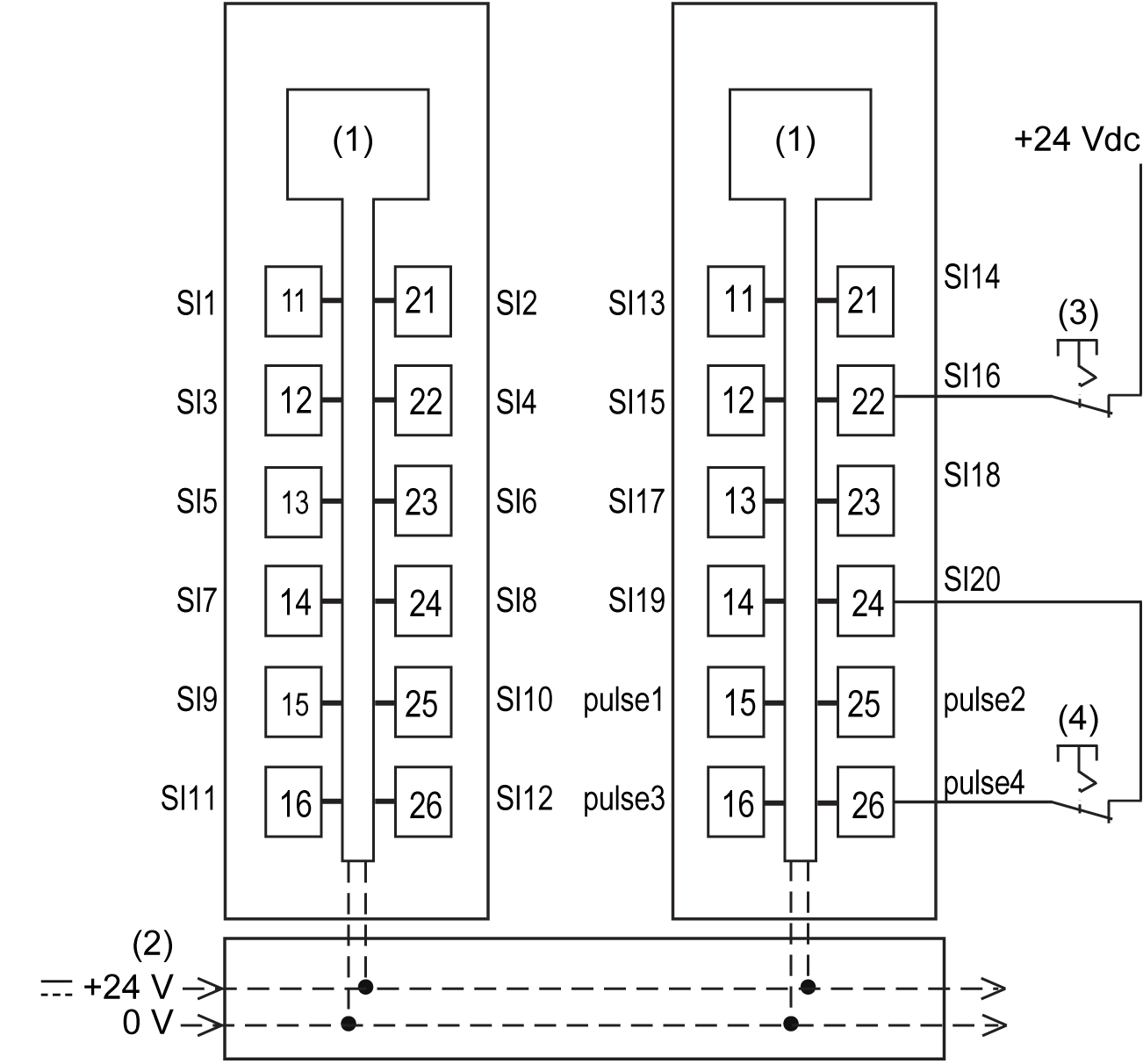
The following figure presents a connection example for the TM5SDI20DFS:

1 Internal electronics
2 24 Vdc I/O power segment integrated into the bus bases
3 Single wire sensor, external power supply
4 Single wire sensor, internally supplied by test (pulse) output
NOTE: When connecting a sensor via an external power supply, it must be the same source as that of the 24 Vdc I/O power segment.
| WARNING | |
|---|---|
| WARNING | |
|---|---|