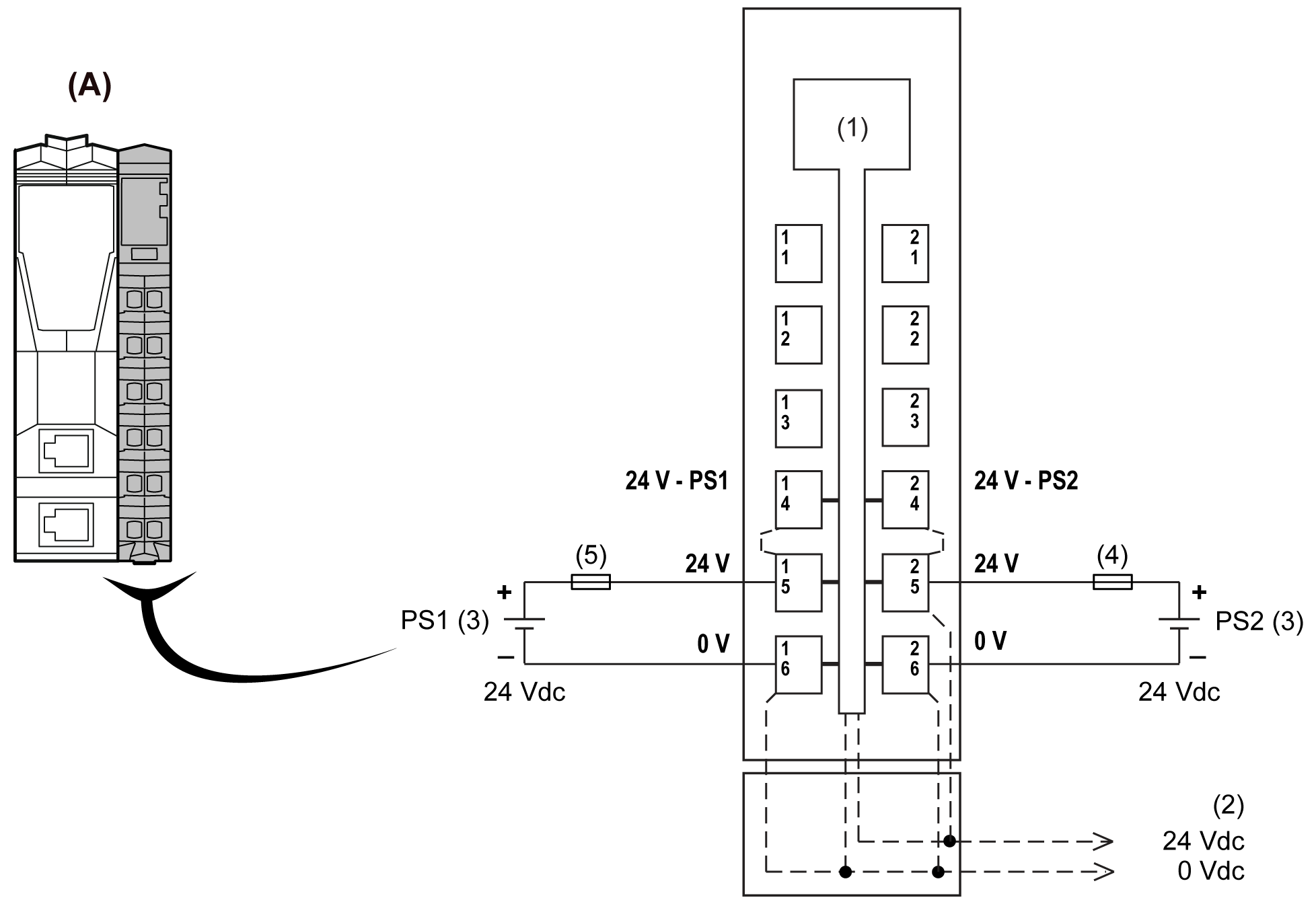
TM5SPS3 Wiring Diagram
Wiring Diagram
The following figure shows the wiring diagram for the TM5SPS3 interface power distribution module:

(A) Interface Power Distribution Module (IPDM)
(1) Internal electronics
(2) 24 Vdc I/O power segment integrated in the bus bases
(3) PS1/PS2: External isolated power supply 24 Vdc
(4) External fuse, Type T slow blow, 10 A maximum, 250 V
(5) External fuse, Type T slow blow, 1 A, 250 V
| WARNING | |
|---|---|
| WARNING | |
|---|---|