|
1
|
Extend the telescopic axis to its entire length, then retract the same and verify its resistance.
NOTE: A light irregular resistance is normal and caused by the manufacturing tolerances of the tubes. The axis is run in during the first 100 hours of operation.
|
|
2
|
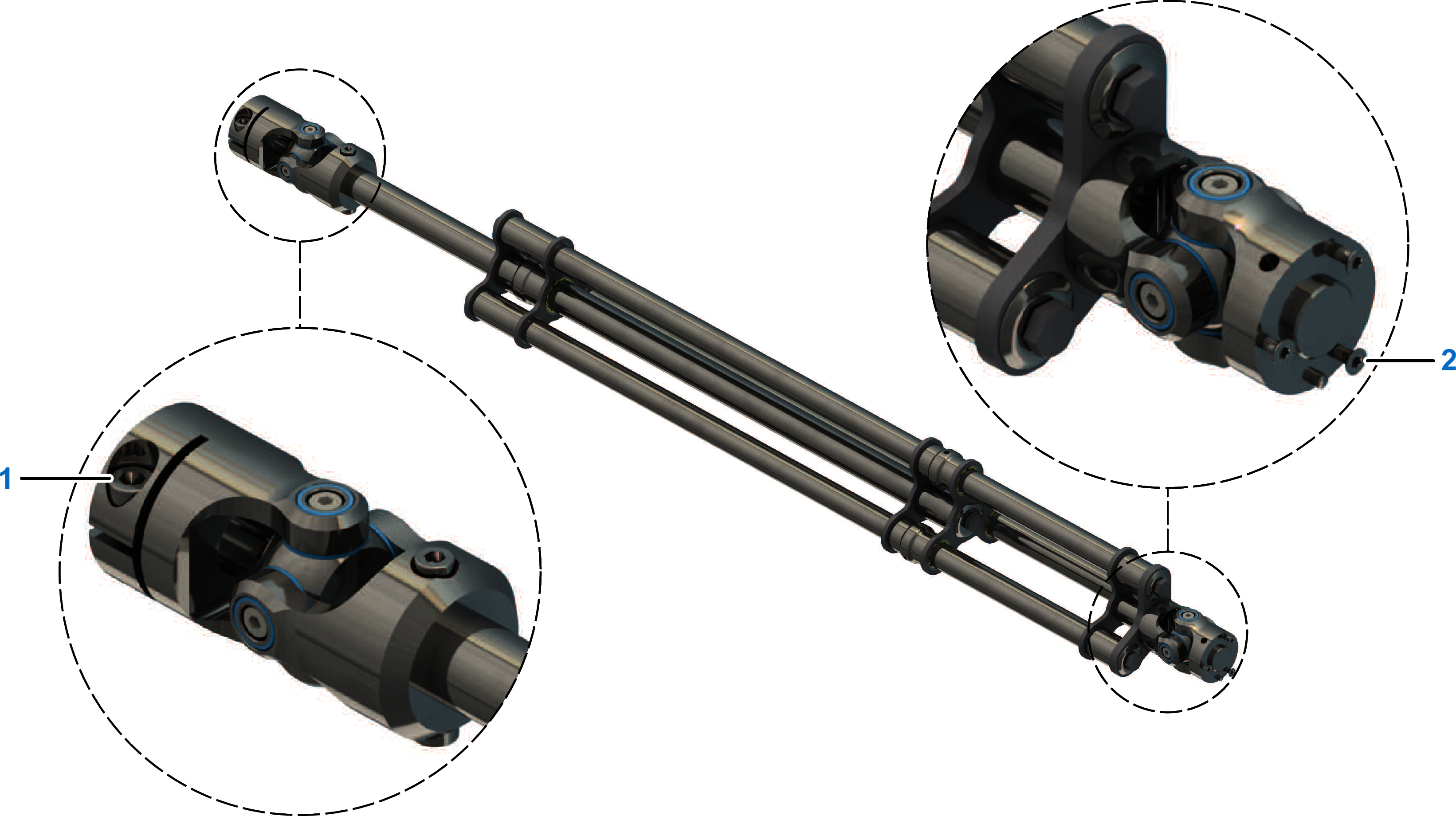
Loosen the clamping screw (1) at the top universal joint.
|
|
3
|
Remove the three countersunk screws (2) from the underside of the bottom universal joint.
|
|
4
|
Place the parallel plate on the bottom universal joint as shown in the following figure and ensure that the locating pin (3) is in alignment with the corresponding hole of the parallel plate (4).
NOTE: In the delivery condition, the index pin is located in the universal joint of the telescopic axis. During dismounting, it may be located in the parallel plate.
|
|
5
|
Attach the parallel plate to the universal joint by using the three countersunk screws that were removed previously. Use the high strength retaining compound Loctite 648 for this purpose.
Tightening torque: 1 Nm (8.9 lbf-in)
NOTE: Apply the high strength retaining compound Loctite 648 into the tapped holes as opposed to applying it to the screws.
|
|
6
|
Push the universal joint (6) over the shaft (7) protruding from the robot housing until the universal joint comes into its stop position on the gear shaft flange. In doing so, rotate the universal joint to ensure that the recess in the universal joint is located above the keyway (5).
|
|
7
|
Tighten the clamping screw (1) that was loosened previously.
Tightening torque: 7.4 Nm (65 lbf-in)
|