Connecting the Connection Module to the Track
Wiring Example
Also refer to Additional Wiring Examples.
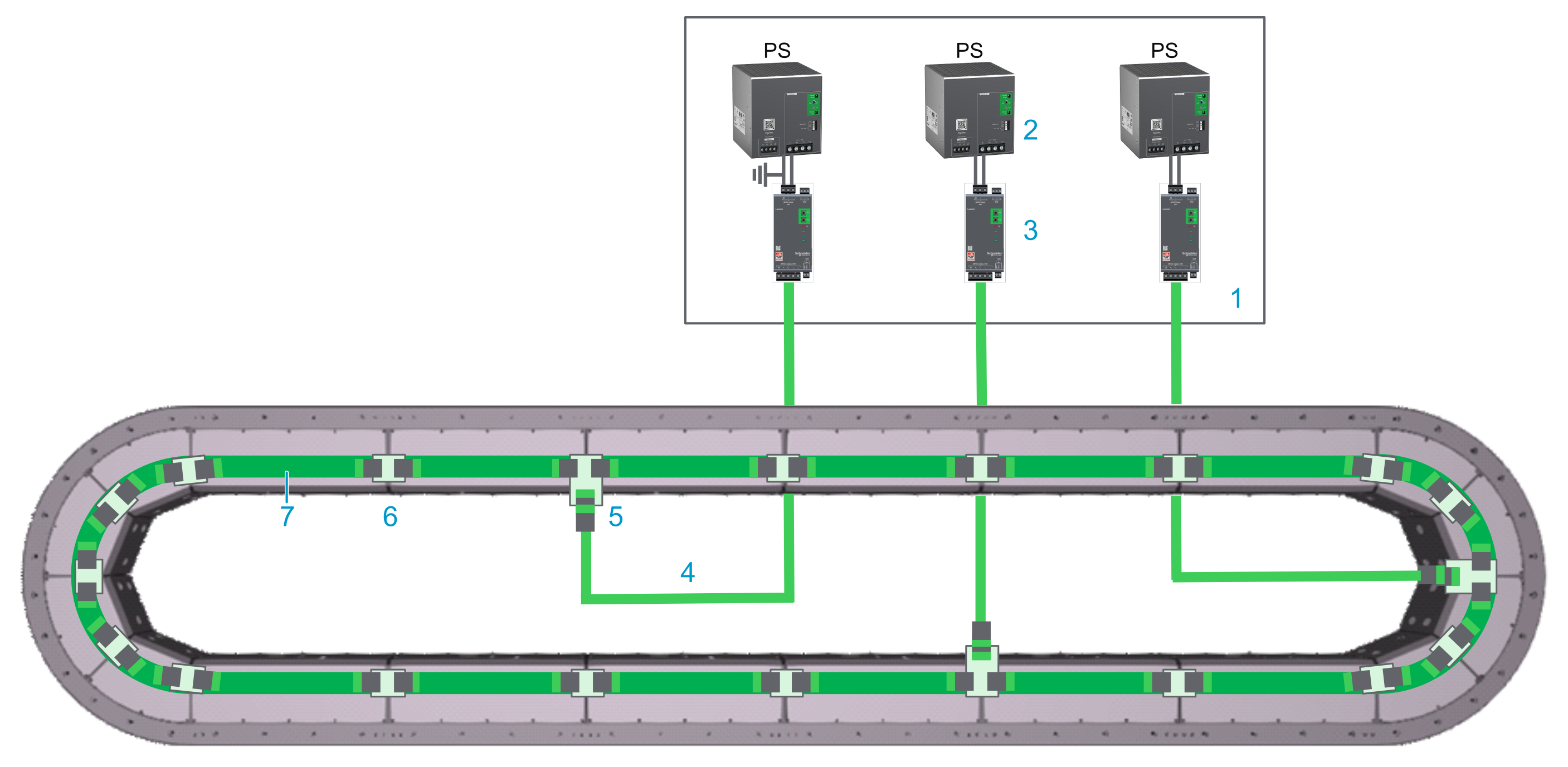
Closed track
|
Element |
Description |
|---|---|
|
1 |
Control cabinet |
|
2 |
Power supply |
|
3 |
Lexium™ MC connection module |
|
4 |
Lexium™ MC power cable with socket connector |
|
5 |
Lexium™ MC power interconnect with plug connector |
|
6 |
Lexium™ MC power interconnect without connector |
|
7 |
Internal DC bus connection |
Description
-
The Lexium™ MC12 multi carrier track is connected to the Lexium™ MC connection module with pre-assembled cables.
NOTE: The front covers of the segments are not connected to the PE (protective ground/earth). The electrical safety requirements are fulfilled by appropriate insulation measures (protective separation). -
The Lexium™ MC connection module supplies the Lexium™ MC12 multi carrier track with power (DC bus).
The Lexium™ MC connection module limits the DC bus voltage to <60 Vdc, conforming to Functional Safety rules. Refer to Scope of Operation (Designated Safety Function).
-
The DC bus (up to 60 A) in the Lexium™ MC12 multi carrier track is distributed from segment to segment via the Lexium™ MC power interconnects.
-
The Lexium™ MC12 multi carrier requires the power supply to be dimensioned based on the number of segments, segment groups, carriers, load and other relevant parameters.
Each power supply/Lexium™ MC connection module combination must not exceed 24 segments.
Also refer to Information About Power Supply/Connection Module.
Connecting the Lexium™ MC connection module to the Lexium™ MC12 multi carrier Track
The following describes the connection from the Lexium™ MC connection module to the Lexium™ MC12 multi carrier track (refer to Wiring Example):
|
Step |
Action |
|---|---|
|
1 |
Connect the Lexium™ MC power cable to the Lexium™ MC connection module CN3 (3) in the wiring example above. |
|
2 |
Connect the Lexium™ MC power cable (4) to the Lexium™ MC power interconnect (5) at the bottom of a segment. Verify that connector of the cable is fixed with its four M3x12 screws to the Lexium™ MC power interconnect, with a torque of 1.2 Nm (10.62 lbf-in). |
Pinout and Cable Diagram
Pinout
Pre-assembled Lexium™ MC power cable. Refer to Type Code.
Only operate the Lexium™ MC12 multi carrier with approved, specified cables, accessories and replacement equipment by Schneider Electric.
| DANGER | |
|---|---|
| DANGER | |
|---|---|
|
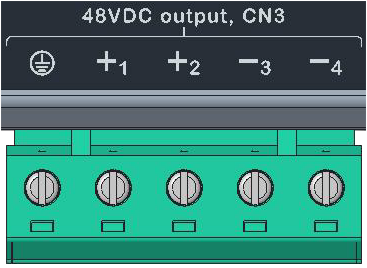
Connector at the Lexium™ MC connection module (CN3) |
Pin from CN3 |
Description |
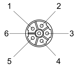
Pin from M23 connector |
Connector (M23, plug) at the Lexium™ MC12 multi carrier track |
|---|---|---|---|---|
|

|
Protective ground (earth) |
3 |
|
|
+1 |
48 Vdc DC bus voltage + |
2 |
||
|
+2 |
Not connected |
1 |
||
|
-3 |
48 Vdc DC bus voltage - |
4 |
||
|
-4 |
Not connected |
5 |
||
|
Not connected |
6 |
|||
|
Cable diagram Shield connected to housing on connector side. 
|
||||
| WARNING | |
|---|---|
An incorrect wiring may result in damage of components.
| CAUTION | |
|---|---|
Additional Wiring Examples
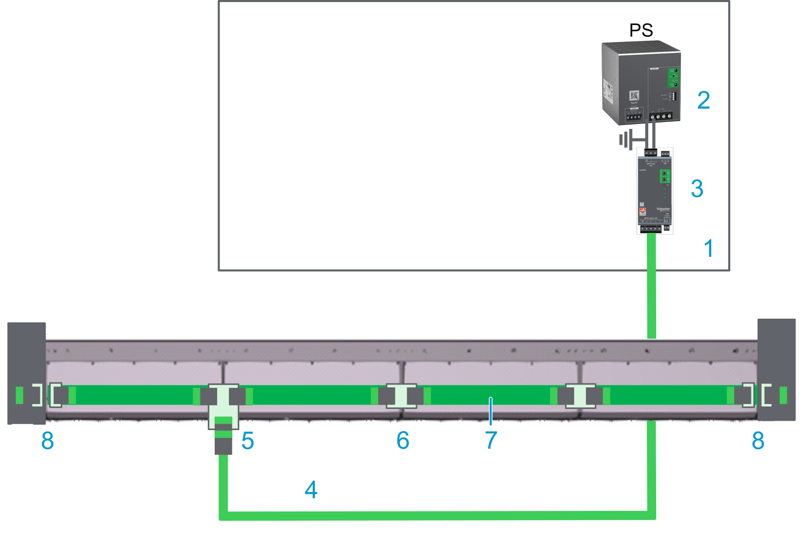
Open track
With an open track, you need a power disconnector (8) at each end of your track.
Also refer to Open Track.
|
Element |
Description |
|---|---|
|
1 |
Control cabinet |
|
2 |
Power supply |
|
3 |
Lexium™ MC connection module |
|
4 |
Lexium™ MC power cable with socket connector |
|
5 |
Lexium™ MC power interconnect with plug connector |
|
6 |
Lexium™ MC power interconnect without connector |
|
7 |
Internal DC bus connection |
|
8 |
Power disconnector |
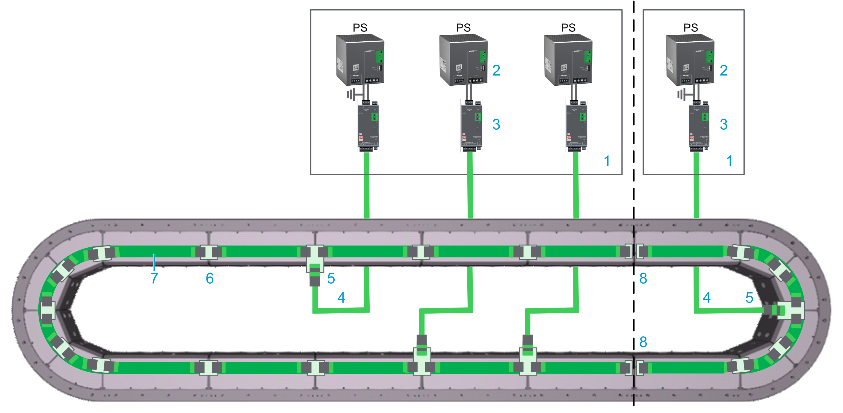
Track with two power supply groups
With a track with two power supply groups, you need power disconnectors (8) between the two power supply groups.
|
Element |
Description |
|---|---|
|
1 |
Control cabinet |
|
2 |
Power supply |
|
3 |
Lexium™ MC connection module |
|
4 |
Lexium™ MC power cable with socket connector |
|
5 |
Lexium™ MC power interconnect with plug connector |
|
6 |
Lexium™ MC power interconnect without connector |
|
7 |
Internal DC bus connection |
|
8 |
Power disconnector |
To ensure an equal load on the power supplies connected in parallel, the power cables in the same power group must have the same length.
| NOTICE | |
|---|---|