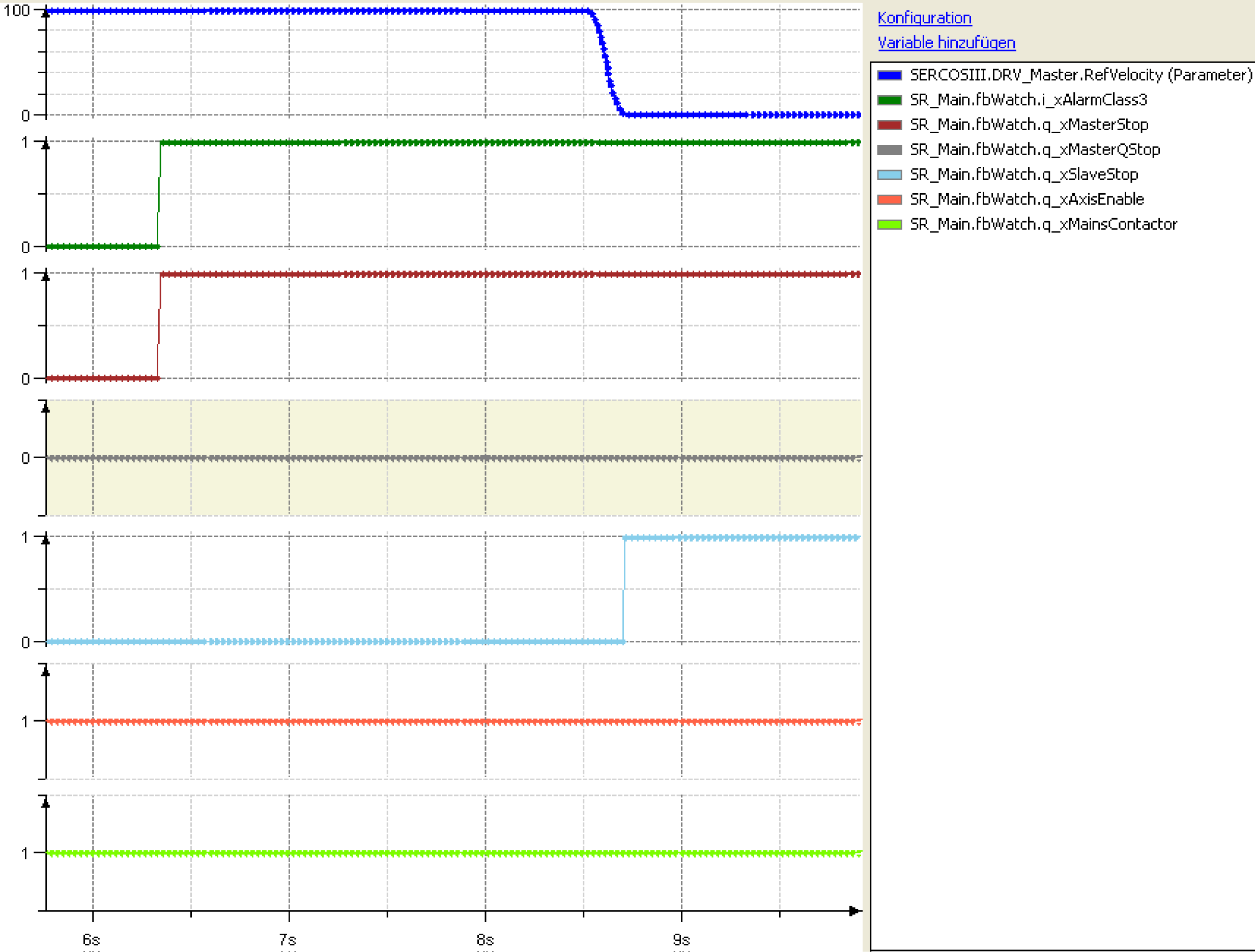
This safety circuit is in compliance with the circuit stipulated by the responsible German professional association [Berufsgenossenschaft]. The PacDrive Controller uses this to monitor the mains voltage. If the emergency stop switch is actuated, the controller stops the axes, without cutting the mains voltage, and switches an auxiliary relay (-K2). Via its contacts a switch-on condition is generated for the mains contactor (K1).
The PacDrive Controller receives the signal of a N/C contact at three digital inputs each. These signals are:
- the state of the mains contactor (here I_MainsWatch),
- the state of the emergency stop switch (here I_EmergencyStop) and
- the state of the emergency stop switch with time delay (here I_InvEnableActive), which stops the drives.
An auxiliary relay -K2 switching the mains contactor (-K1) in connection with the watchdog signals of the controller and the ready signals of the drives is switched via a digital output of the PacDrive Controller (here O_MainsContactor).
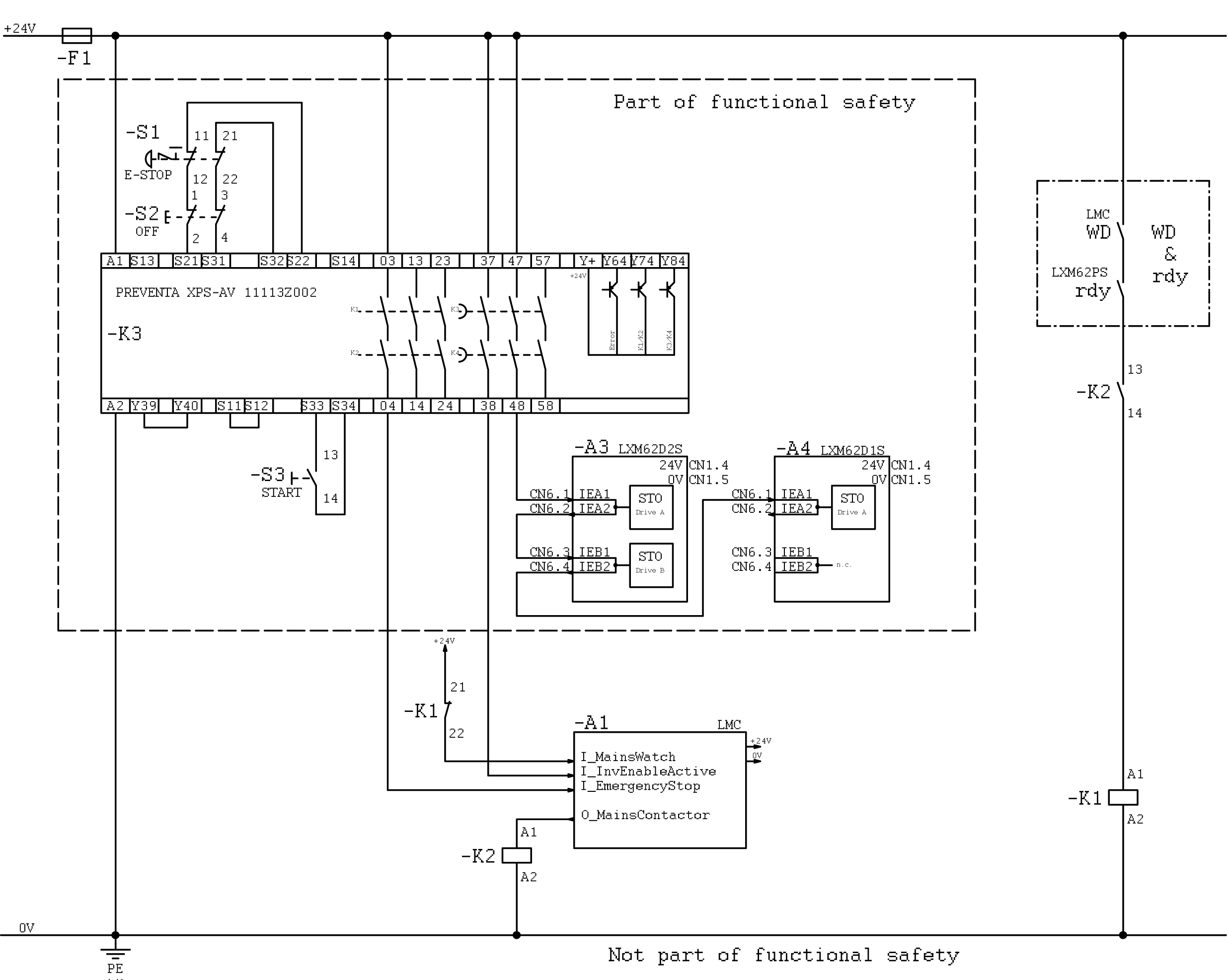
The I_MainsWatch feedback signal of the mains contactor is linked to the i_xMainsWatch input of the FB_Watch function block.
The digital O_MainsContactor output is linked to the q_xMainsContactor output of the FB_Watch.
The I_InvEnable input is checked with the InverterEnable signal of the axes by means of the FB_InverterEnableDiag function block. The result is transferred to the i_xMainsOff input of the FB_Watch.
The q_xMasterStop, the q_xMasterQStop and the q_xSlaveStop outputs of the FB_Watch are linked to controller signals of the master and slave axes of the machine.
The machine can then be stopped via the i_xAlarmClass1 up to the i_xAlarmClass3 input of the FB_Watch.
NOTE: The displayed program example only serves as a demonstration for the use of the FB_Watch function block and is not suitable for the direct use in production machines. It does not contain a logic to acklowledge alarms nor to control the machine, as it is usual for physical machines.
The three following machine reactions can be realized via the i_xAlarmClass1 up to the i_xAlarmClass3 inputs.
Alarm class 1 has the highest priority, followed by class 2 and 3. This means that the execution of an alarm can be replaced by a higher priority alarm.
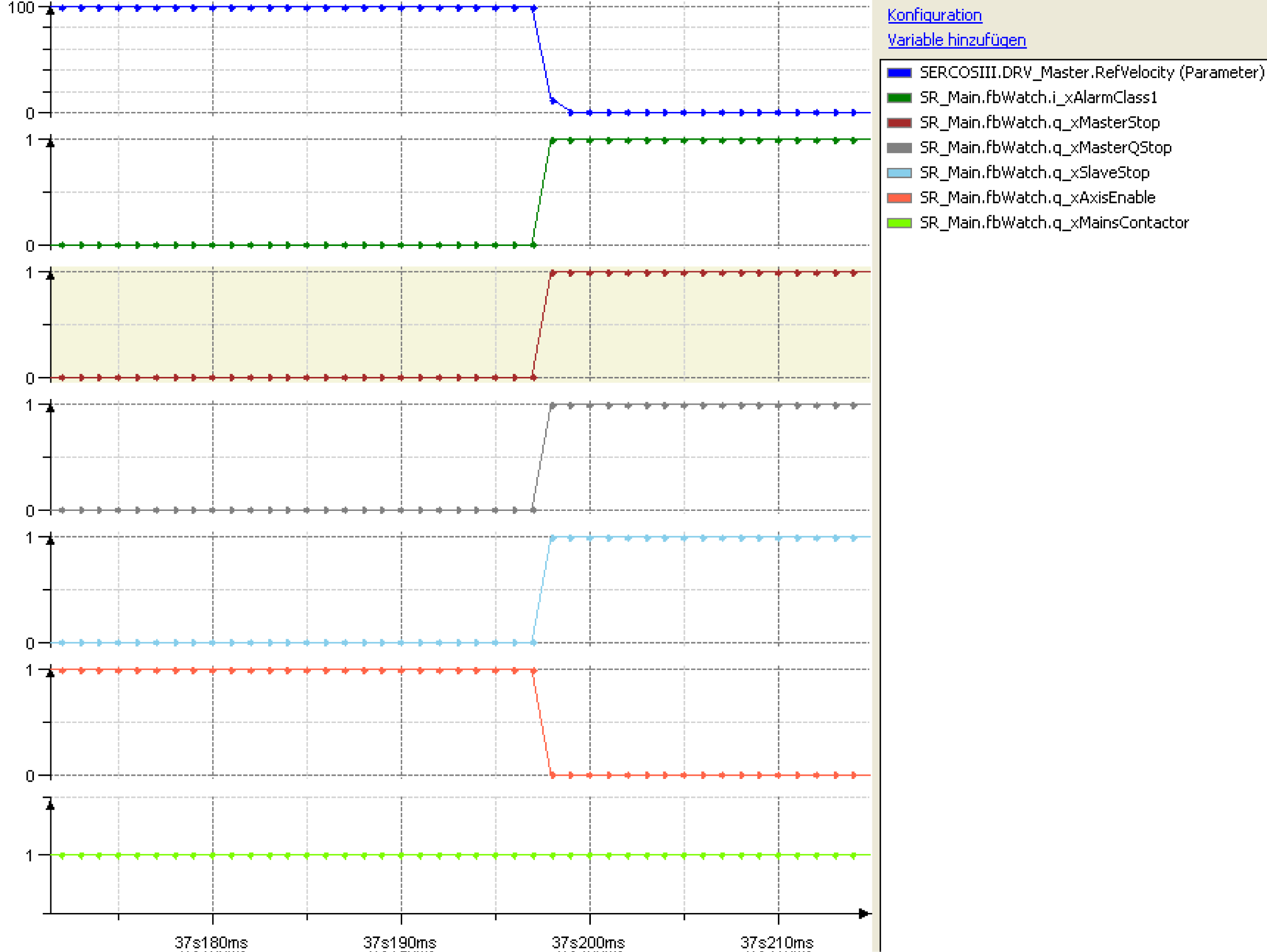
i_xAlarmClass1:
oall axes are stopped in the best manner possible,
othe drives stop asynchronously to one another,
oq_xAxisEnable is switched off,
owhen the safety wiring is used, the mains contactor is not de-energized.
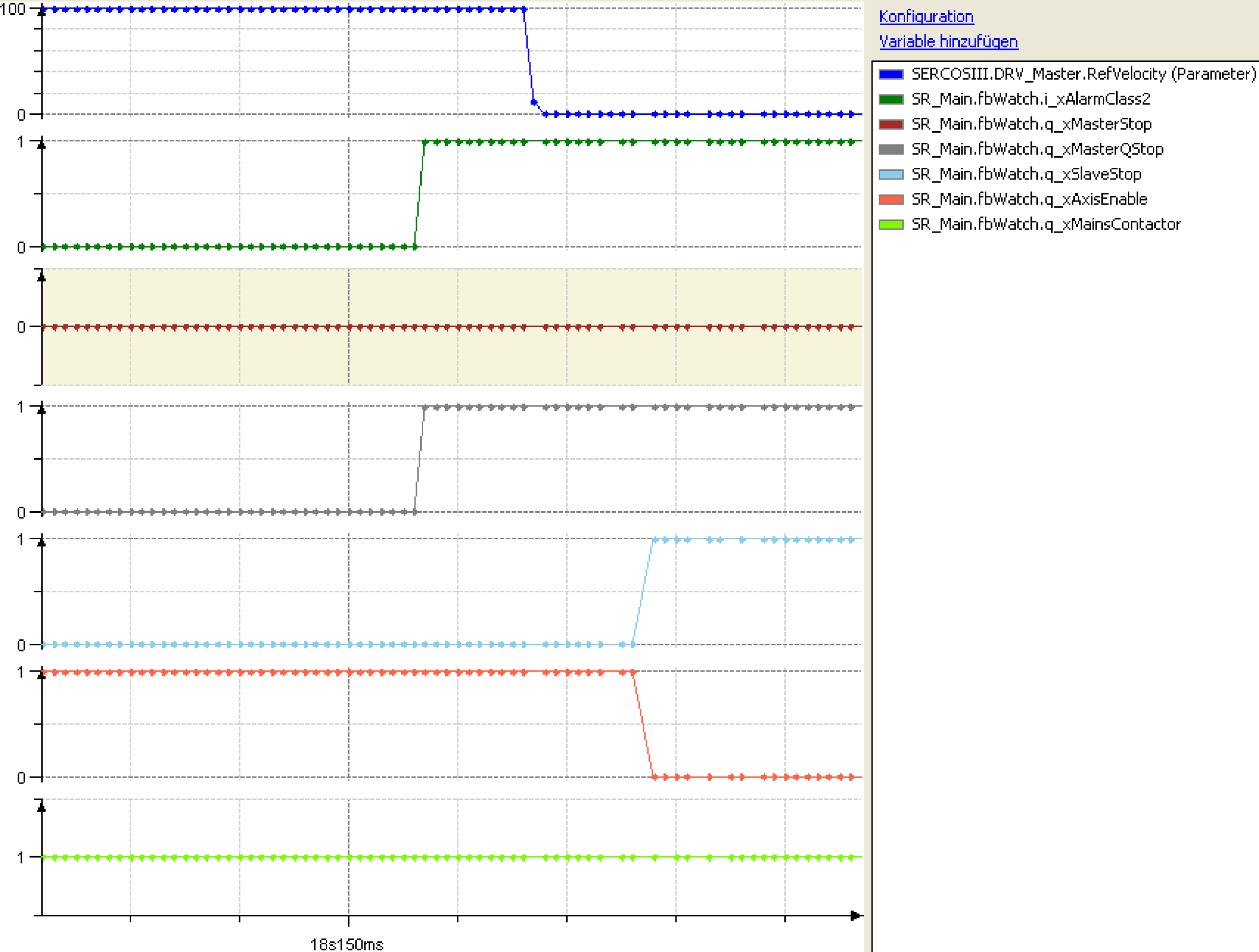
i_xAlarmClass2:
othe master axis is stopped immediately,
othe slave axes are stopped synchronously with the master axis
oq_xAxisEnable is switched off,
owhen the safety wiring is used, the mains contactor is not de-energized.
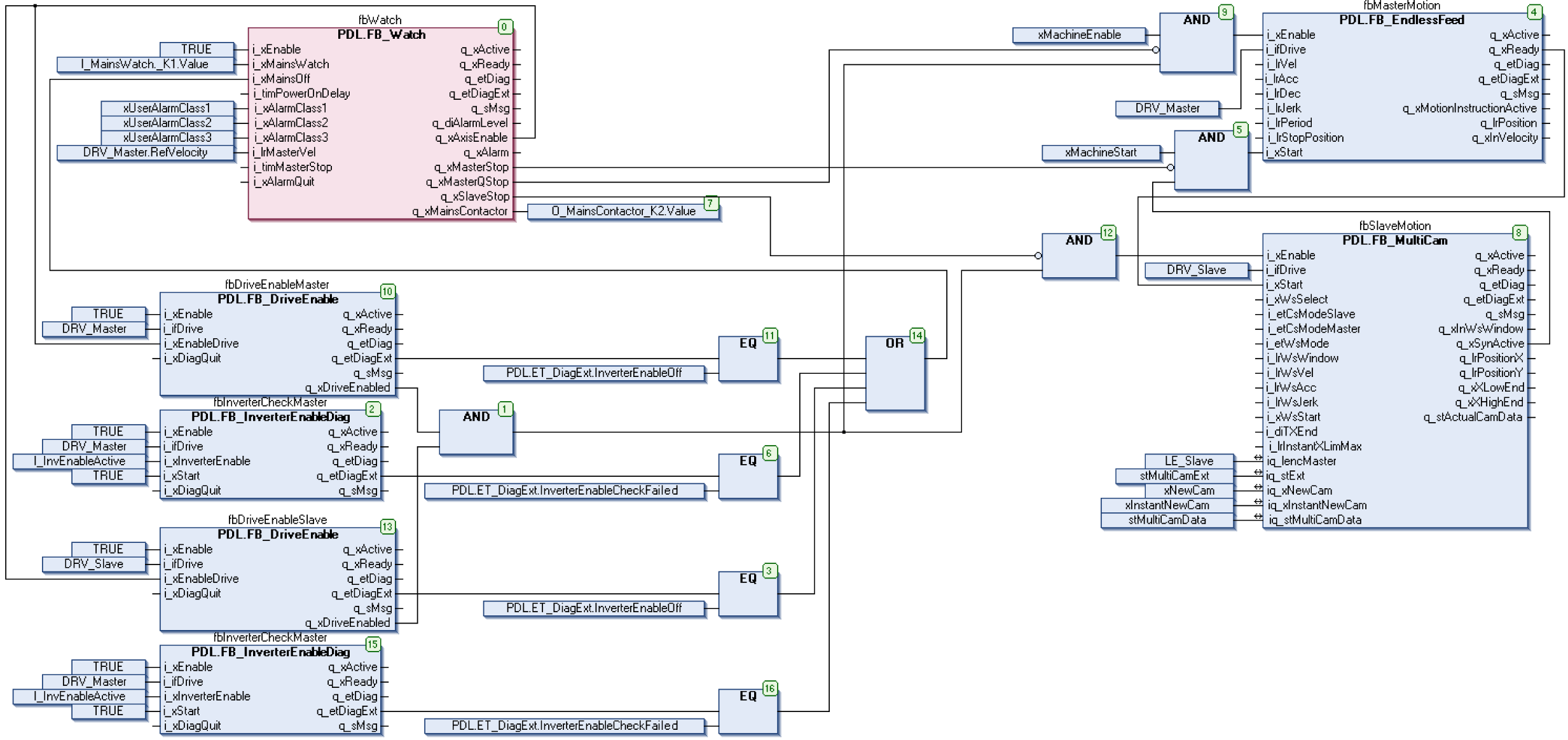
i_xAlarmClass3:
othe master axis is stopped at the end of the cycle,
othe slave axes are stopped synchronously with the master axis
oq_xAxisEnable is not switched off,
owhen the safety wiring is used, the mains contactor is not de-energized.
