Slices Installation
Introduction
The installation procedure of the slices is to install and assemble them directly on the DIN rail:
| 1 |
Mount the bus bases. |
| 2 |
Insert the electronic modules. |
| 3 |
Mount the terminal blocks. |
| DANGER | |
|---|---|
The installation procedure for the first bus base depends whether it is a local, remote or distributed configuration.
| NOTICE | |
|---|---|
Mounting the Bus Bases
The following procedure describes how to mount the bus bases:
|
Step |
Description |
|
|---|---|---|
|
1 |
Remove bus bases from protective packaging. Verify the bus bases for visible mechanical damage. |
|
|
2 |
Push the locking lever all the way up on all of the bus bases. This opens the locking mechanism. |
|
|
3 |
|
|
|
4 |
|
|
|
5 |
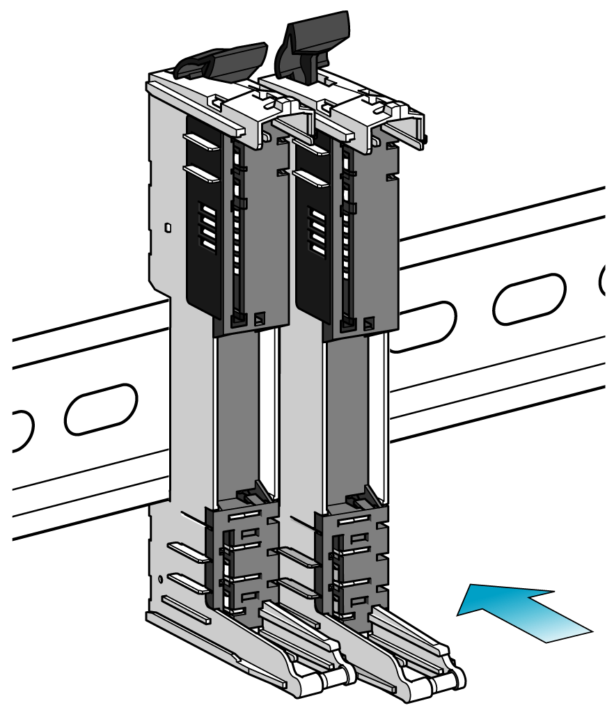
Insert the next bus base in the guides of the previously mounted bus base. |
|
|
6 |
Slide the bus base in against the mounting rail and secure it by pushing down the locking lever. |
|
|
7 |
According to the installation plan, proceed like this with the rest of the bus bases. |
|
|
8 |
If using bus bases with address setting, assign the bus base address at this step of the installation procedure of the slices. |
|
Inserting the Electronic Modules
A slice must only be composed of a single color. For example, a gray bus base should only be assembled with a gray electronic module and a gray terminal block. However, color alone is not sufficient for compatibility; always confirm that functionality of slice components matches as well.
| DANGER | |
|---|---|
The following procedure describes how to mount the electronic modules:
|
Step |
Action |
|
|---|---|---|
|
1 |
Remove electronic module from protective packaging. Verify the electronic module for visible mechanical damage. |
|
|
2 |
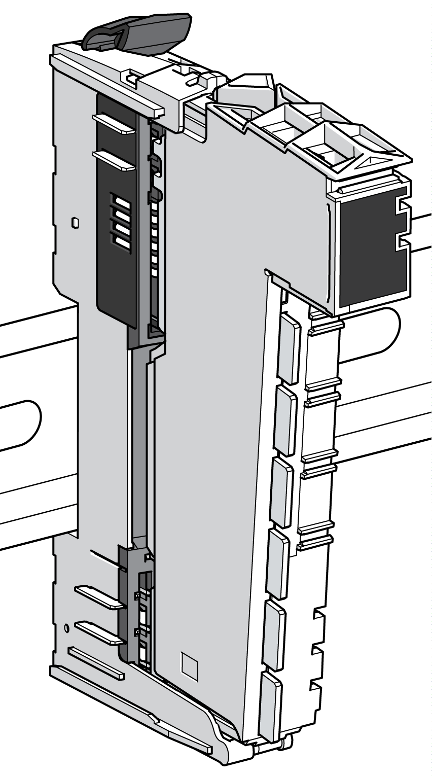
Insert electronic module in the guides of the bus base. |
|
|
3 |
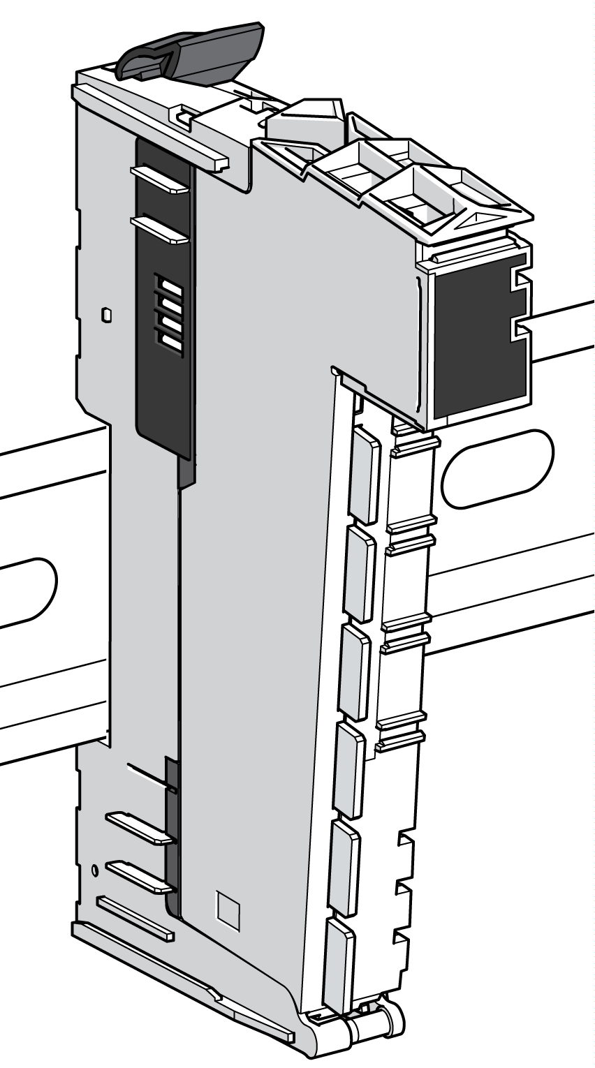
Push the electronic module straight into the bus base until it clicks. |
|
|
4 |
According to the installation plan, proceed like this with all the electronic modules. |
|
Mounting the Terminal Blocks
A slice must only be composed of a single color. For example, a gray bus base should only be assembled with a gray electronic module and a gray terminal block. However, color alone is not sufficient for compatibility; always confirm that functionality of slice components matches as well.
| DANGER | |
|---|---|
See Coding the TM5 System for assistance in labeling and associating components.
The following procedure describes how to mount the terminal block:
|
Step |
Action |
|
|---|---|---|
|
1 |
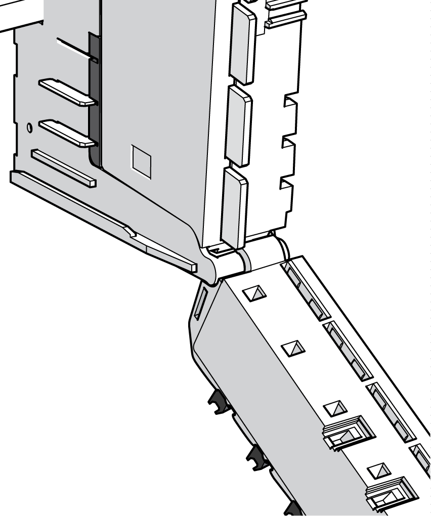
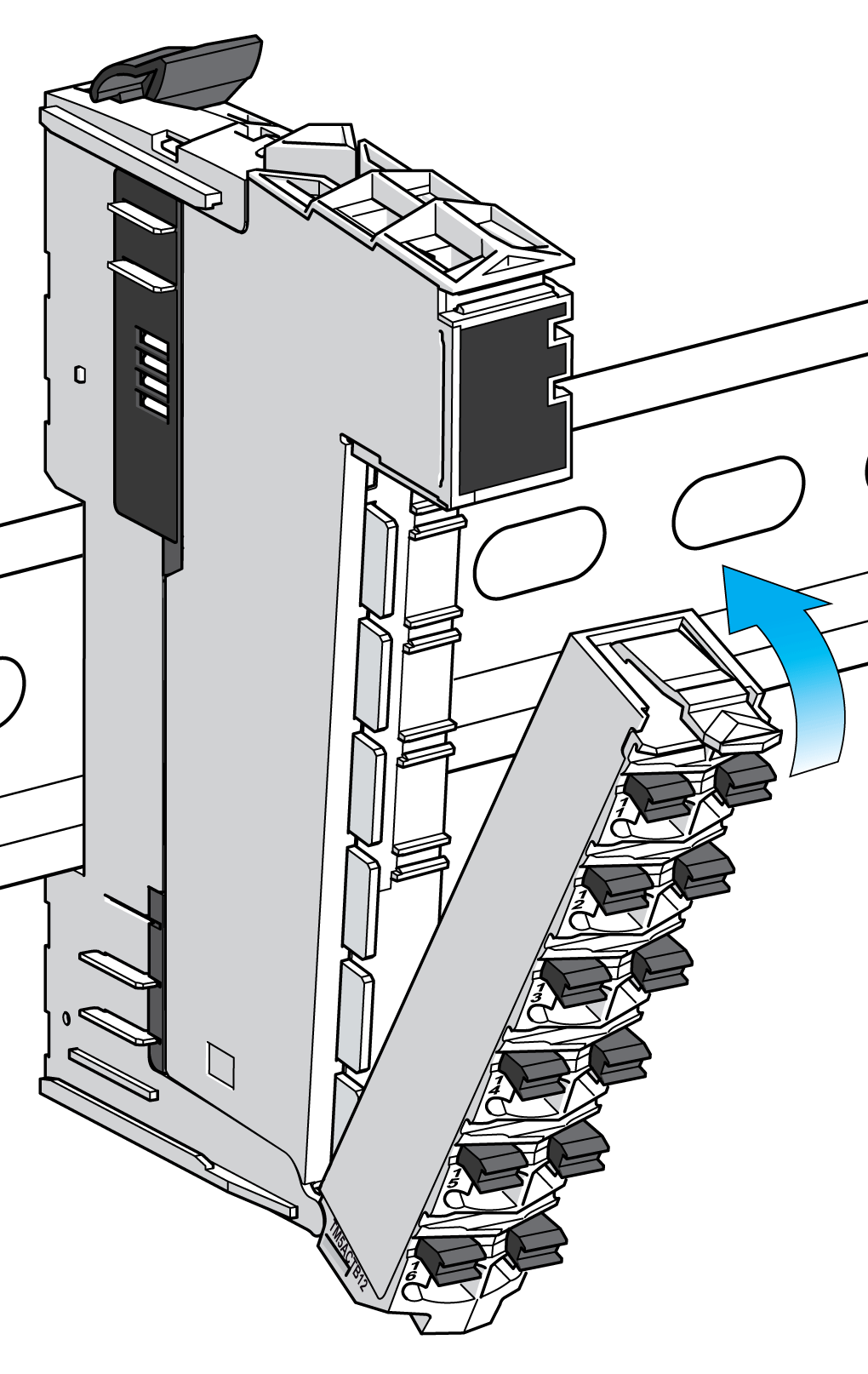
Hang the bottom edge of the terminal block in its hinge on the bus base. |
|
|
2 |
Rotate upward. |
|
|
3 |
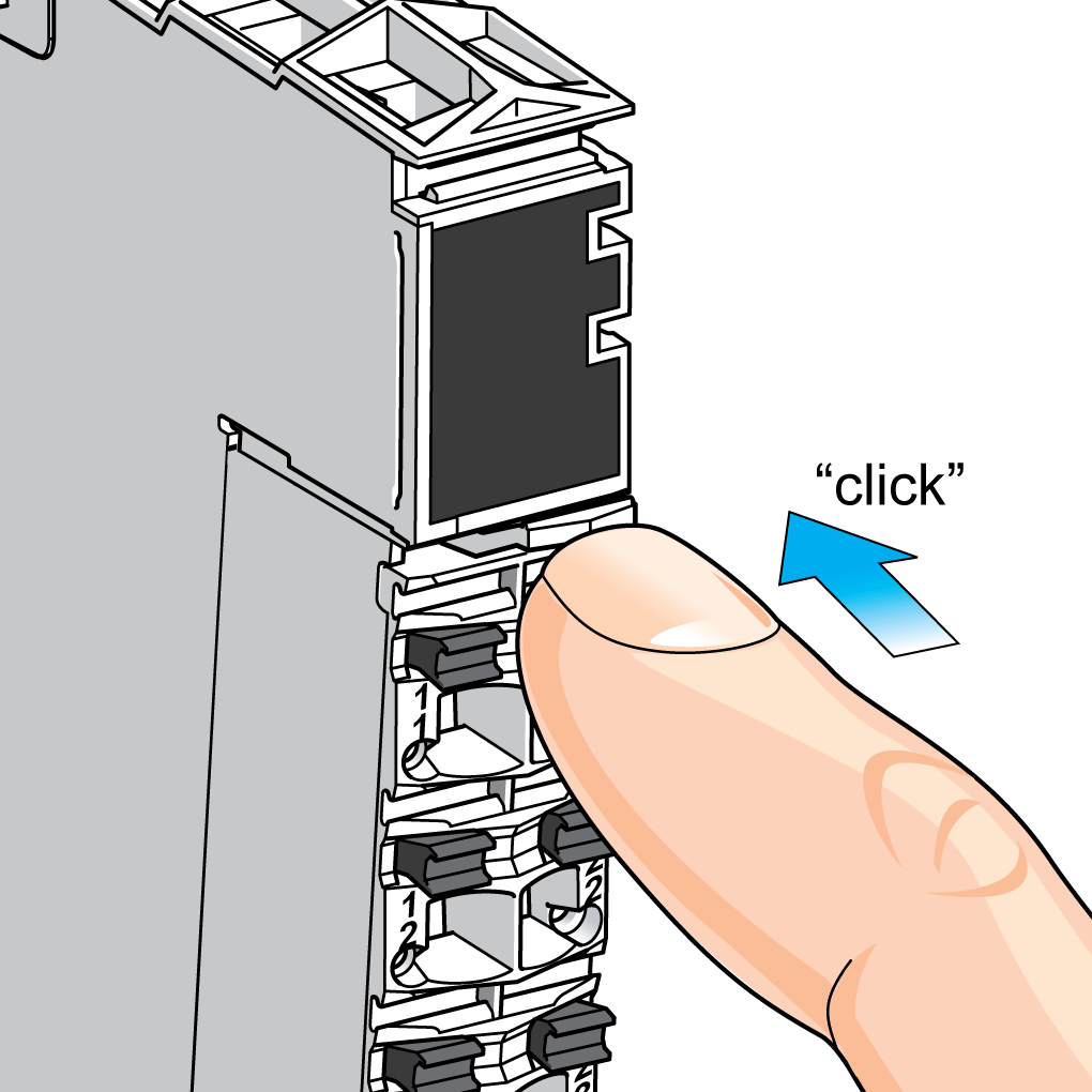
Press the terminal block until it clicks in place. |
|
|
4 |
According to the installation plan, proceed like this with all the terminal blocks. |
|
Right Bus Base Locking Plate
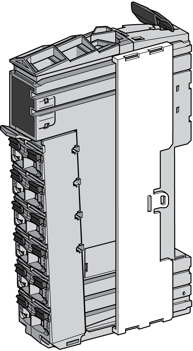
The right bus base locking plate must be attached to the rightmost slice of the Sercos III Bus Interface or the rightmost expansion module of the remote configuration, or distributed island:
|
Step |
Action |
|
|---|---|---|
|
1 |
Remove the terminal block of the rightmost expansion module . |
|
|
2 |
From the front, insert the right bus base locking plate into the bus base interlocking guides. |
|
|
3 |
Push it in all the way. |
|
|
4 |
Replace the terminal block of the rightmost expansion module. |
|
Left Bus Base Locking Plate
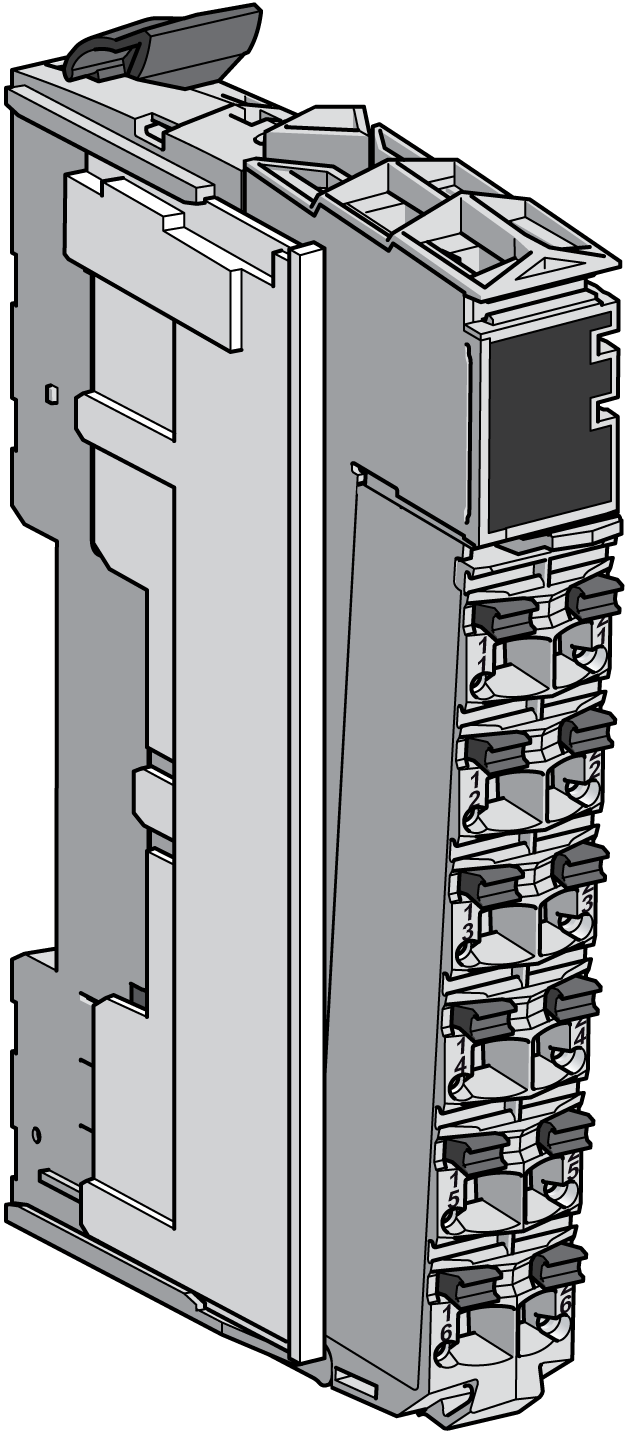
The left bus base locking plate is attached to the first slice (receiver slice) of the remote islands:
|
Step |
Action |
|
|---|---|---|
|
1 |
Place the left bus base locking plate on the left slice and insert it in the interlocking guides of the terminal block. |
|
|
2 |
Slide the bus base locking plate forward. |
|