TM5 Safety-Related System Terminal Block
Overview
The main features of the terminal blocks are:
-
Tool-free wiring with spring clamp push-in technology
-
Simple push-button wire release
-
Ability to label each terminal
-
Plain text labeling also possible
-
Test access for standard probes
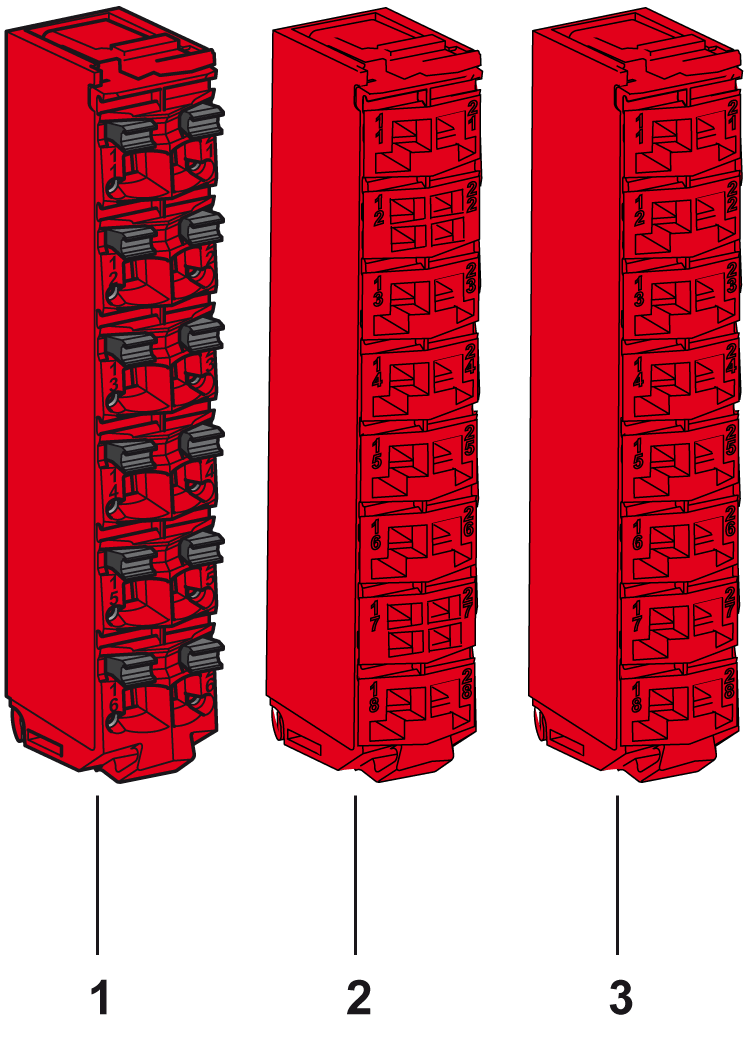
The following figure shows the TM5 Safety-Related System terminal block:

|
Number |
Reference |
Description |
Color |
|---|---|---|---|
|
1 |
TM5ACTB52FS |
24 Vdc / 230 Vac, 12-pin terminal block for safety-related modules and Safety Logic Controller, safety coded |
Red |
|
2 |
TM5ACTB5EFS |
24 Vdc, 16-pin terminal block for safety-related modules, safety coded, 2x PT1000 integrated for terminal temperature compensation |
Red |
|
3 |
TM5ACTB5FFS |
24 Vdc, 16-pin terminal block for safety-related modules, safety coded |
Red |
A slice must only be composed of a single color. For example, a gray bus base should only be assembled with a gray electronic module and a gray terminal block. However, color alone is not sufficient for compatibility; always confirm that functionality of slice components matches as well.
| DANGER | |
|---|---|
General Characteristics
| DANGER | |
|---|---|
| WARNING | |
|---|---|
| WARNING | |
|---|---|
The following table shows the technical data for TM5 Safety-Related System terminal block, see also environmental characteristics:
|
General Characteristics |
||
|---|---|---|
|
Type of terminal |
Spring-clamp push-in terminal |
|
|
Contact resistance |
≤ 5 mΩ |
|
|
Maximum voltage(1) |
TM5ACTB52FS |
253 Vac |
|
TM5ACTB5EFS |
50 Vdc |
|
|
TM5ACTB5FFS |
||
|
Current(1) |
TM5ACTB52FS |
10 A maximum per connector |
|
TM5ACTB5EFS |
2 A maximum per connector |
|
|
TM5ACTB5FFS |
||
|
Weight |
TM5ACTB52FS |
20 g (0.7 oz) |
|
TM5ACTB5EFS |
||
|
TM5ACTB5FFS |
||
|
Connection cross section |
TM5ACTB52FS |
|
|
Solid wire line Fine wire line With wire cable end With double wire cable end |
0.08 mm²...2.5 mm² (AWG 28...14) 0.25 mm²...2.5 mm² (AWG 24...14) 0.25 mm²...1.5 mm² (AWG 24...16) 2 x 0.25...2 x 0.75 mm² (AWG 2 x 24...2 x 18) |
|
|
TM5ACTB5EFS TM5ACTB5FFS |
||
|
Solid wire line Fine wire line With wire cable end With double wire cable end |
0.08 mm²...1.5 mm² (AWG 28...16) 0.25 mm²...1.5 mm² (AWG 24...16) 0.25 mm²...0.75 mm² (AWG 24...20) - |
|
|
Wire |
Follow the wiring rules. |
|
|
(1) Connected voltage and current depends on I/O electronics modules associated. |
||
| DANGER | |
|---|---|
Maximum Insertion/Removal Cycles
The TM5 System bus bases are designed to withstand up to 50 electronic module insertion/removal cycles.