Safety Logic Controller Description
Description
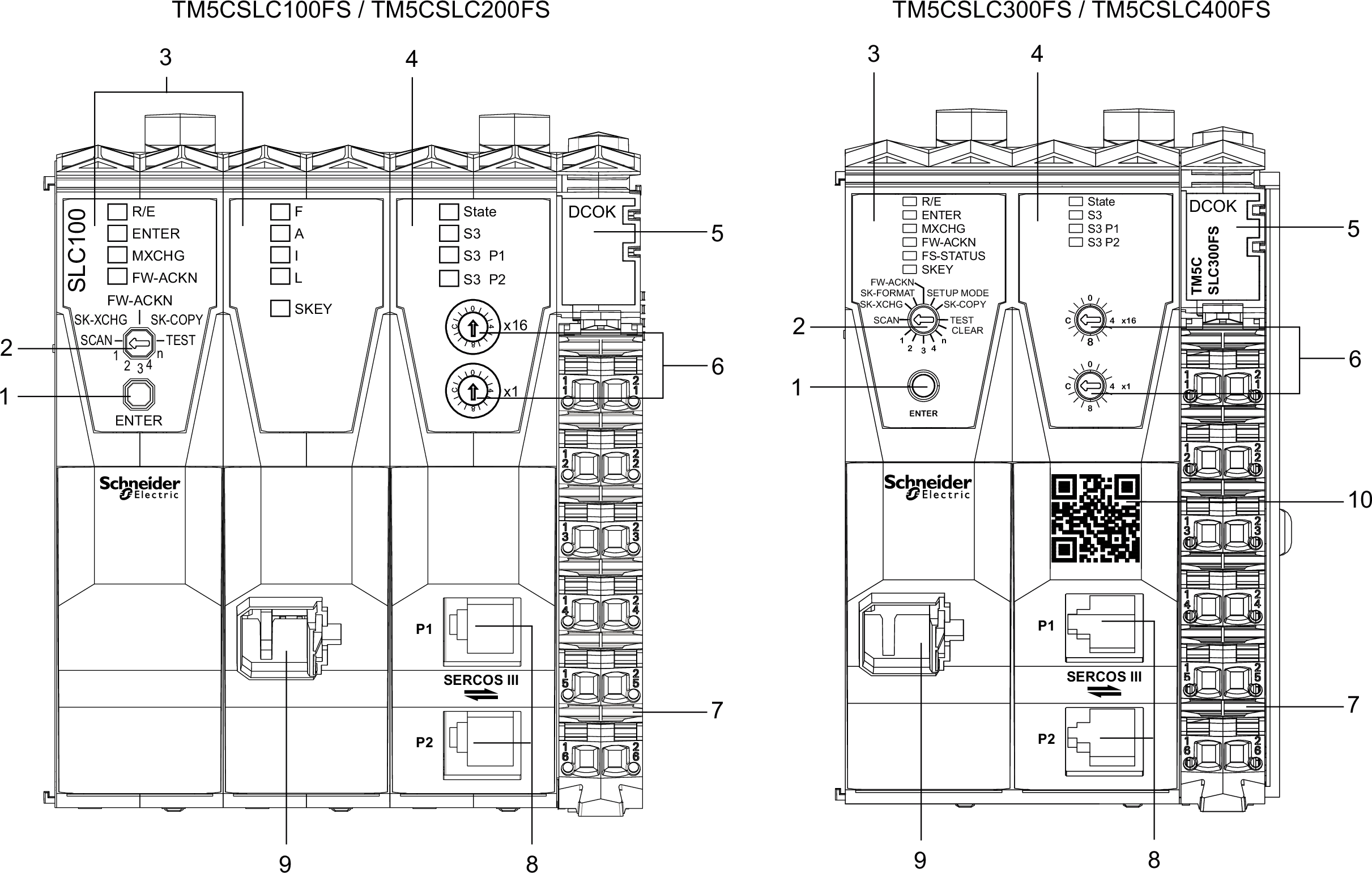
The LED indicators, buttons and switches are integrated to operate the Safety Logic Controller.
The following figure presents the operating and connection elements:

|
N° |
Description |
Reference / Function |
|---|---|---|
|
1 |
Confirmation button |
|
|
2 |
Selection switch |
|
|
3 |
Logic processor |
|
|
4 |
Sercos III interface |
|
|
5 |
Integrated power supply |
|
|
6 |
Sercos address switches |
|
|
7 |
Terminal block for Safety Logic Controller power supply |
|
|
8 |
Sercos III connection with 2 x RJ45 |
|
|
9 |
Memory key slot |
|
|
10 |
QR code |
Scanning the QR code opens the product specific Schneider Electric website. |
These components enable you to perform the following operations:
-
confirm the module replacement
-
confirm the firmware update
-
confirm the memory key replacement, including a possible transfer of module configuration from the previous memory key
-
support for the replacement of Safety Logic Controller