Presentation
A power supply is integrated in the Safety Logic Controller TM5CSLC100FS /TM5CSLC200FS and TM5CSLC300FS / TM5CSLC400FS.
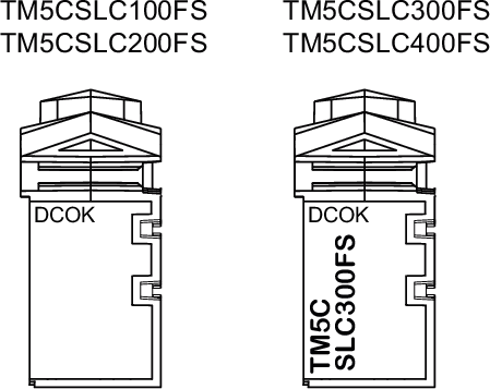
LED indicators
The following figure presents the status LED indicators for integrated power supply:
The following table describes the LED status for the integrated power supply:
|
LED indicator
|
LED color
|
LED status
|
State description
|
|
DCOK
|
green
|
on
|
Power applied to the controller
|
|
off
|
No power applied to the controller
|
Wiring Diagram
|
DANGER
|
|
FIRE HAZARD
Use only the correct wire sizes for the maximum current capacity of the power supplies.
Failure to follow these instructions will result in death or serious injury.
|
|
DANGER
|
|
HAZARD OF ELECTRIC SHOCK, EXPLOSION, OVERHEATING AND FIRE
-
Do not connect the modules directly to line voltage.
-
Use only isolating PELV systems according to IEC 61140 to supply power to the modules.
-
Connect the 0 Vdc of the external power supplies to FE (Functional Earth/ground).
Failure to follow these instructions will result in death or serious injury.
|
The following figure presents the wiring diagram of the power supply for the Safety Logic Controller:
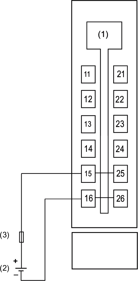
1 Internal electronics
2 External isolated power supply 24 Vdc (-15% / +20%)
3 External fuse, Type T slow-blow, 1 A, 250 V