TM7SDI8DFS Wiring
Connection Elements
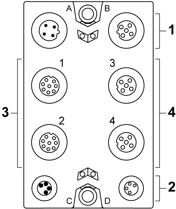
The following figure presents the connection elements for the TM7SDI8DFS:

|
Number |
Meaning |
|---|---|
|
1 |
TM5 link:
|
|
2 |
Module supply 24 Vdc:
|
|
3 |
Connectors 1 and 2:
|
|
4 |
Connectors 3 and 4:
|
Pin Assignments
The pin assignments of the power and communication connectors (A, B, C and D) are provided in the TM7 Physical Description.
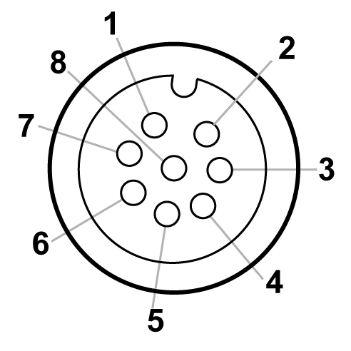
Pin assignment for the 8-pin I/O connectors 1 and 2 of the TM7SDI8DFS module:

1 +24 Vdc
2 Test (pulse) output 1
3 COM
4 SI x (safety-related inputs)
5 DI x
6 Test (pulse) output 2
7 SI x (safety-related inputs)
8 DO x (non-safety-related outputs)
|
Connector socket |
Pin1 |
Pin2 |
Pin3 |
Pin4 |
Pin5 |
Pin6 |
Pin7 |
Pin8 |
|---|---|---|---|---|---|---|---|---|
|
1 (IN/OUT) |
+24 Vdc |
Test (pulse) output 1 |
COM |
SI 1 |
DI 1 |
Test (pulse) output 2 |
SI 2 |
DO 1 |
|
2 (IN/OUT) |
+24 Vdc |
Test (pulse) output 1 |
COM |
SI 3 |
DI 2 |
Test (pulse) output 2 |
SI 4 |
DO 2 |
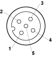
Pin assignment for the 5-pin I/O connectors 3 and 4 of the TM7SDI8DFS module:

1 Test (pulse) x
2 SI x (safety-related inputs)
3 COM
4 SI x (safety-related inputs)
5 Test (pulse) x (inputs)
|
Connector socket |
Pin1 |
Pin2 |
Pin3 |
Pin4 |
Pin5 |
|---|---|---|---|---|---|
|
3 (IN) |
Test (pulse) 1 |
SI 5 |
COM |
SI 6 |
Test (pulse) 2 |
|
4 (IN) |
Test (pulse) 1 |
SI 7 |
COM |
SI 8 |
Test (pulse) 2 |
| WARNING | |
|---|---|