TM5SDI20DFS Characteristics
Introduction
This section describes the characteristics of the TM5SDI20DFS module. See also TM5 Environmental Characteristics.
| DANGER | |
|---|---|
| WARNING | |
|---|---|
General Characteristics
The following table lists the general characteristics of the TM5SDI20DFS module:
|
General characteristics |
||
|---|---|---|
|
Rated power supply voltage |
24 Vdc |
|
|
Integrated protection |
Reverse polarity protection |
|
|
Status indicators |
|
|
|
Diagnostics |
Module run and detected error conditions indicated by status LED indicator and software status. |
|
|
Electrical isolation(1) |
channel - bus |
See note. |
|
channel - channel |
no galvanic isolation |
|
|
TM5 Bus 5 Vdc current draw |
80 mA |
|
|
24 Vdc I/O segment current draw |
66.7 mA |
|
|
Certifications and standards |
Refer to www.se.com for the latest information regarding certifications and standards. |
|
|
Maximum internal cycle time |
1600 µs |
|
|
Minimum cycle time |
200 µs |
|
|
Minimum I/O update time |
800 µs |
|
|
Id code for firmware update |
44744 dec |
|
NOTE (1) The isolation of the electronic module is 500 Vac RMS between the electronics power by the TM5 bus and those powered by 24 Vdc I/O power segment connected to the module. In practice, the electronic module is installed in the bus base, and there is a bridge between the TM5 power bus and the 24 Vdc I/O power segment. The two power circuits reference the same functional ground (FE) through specific components designed to reduce effects of electromagnetic interference. These components are rated at 30 Vdc or 60 Vdc. This effectively reduces isolation of the entire system from the 500 Vac RMS.
Operating Conditions
The following table lists the operating conditions for the TM5SDI20DFS module:
|
Operating conditions |
||
|---|---|---|
|
Mounting orientation |
horizontal or vertical |
|
|
Operating temperature |
horizontal installation |
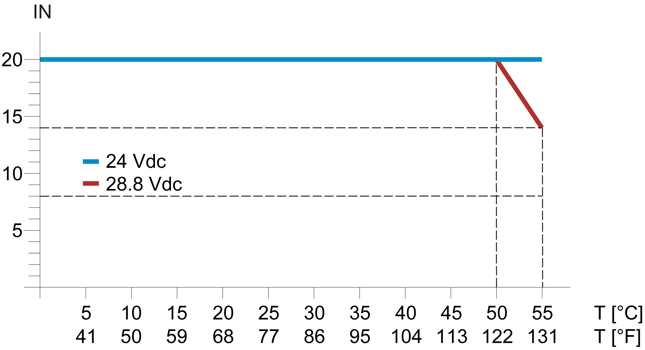
0...+55 °C (+32...131 °F), for derating refer to following table1 |
|
vertical installation |
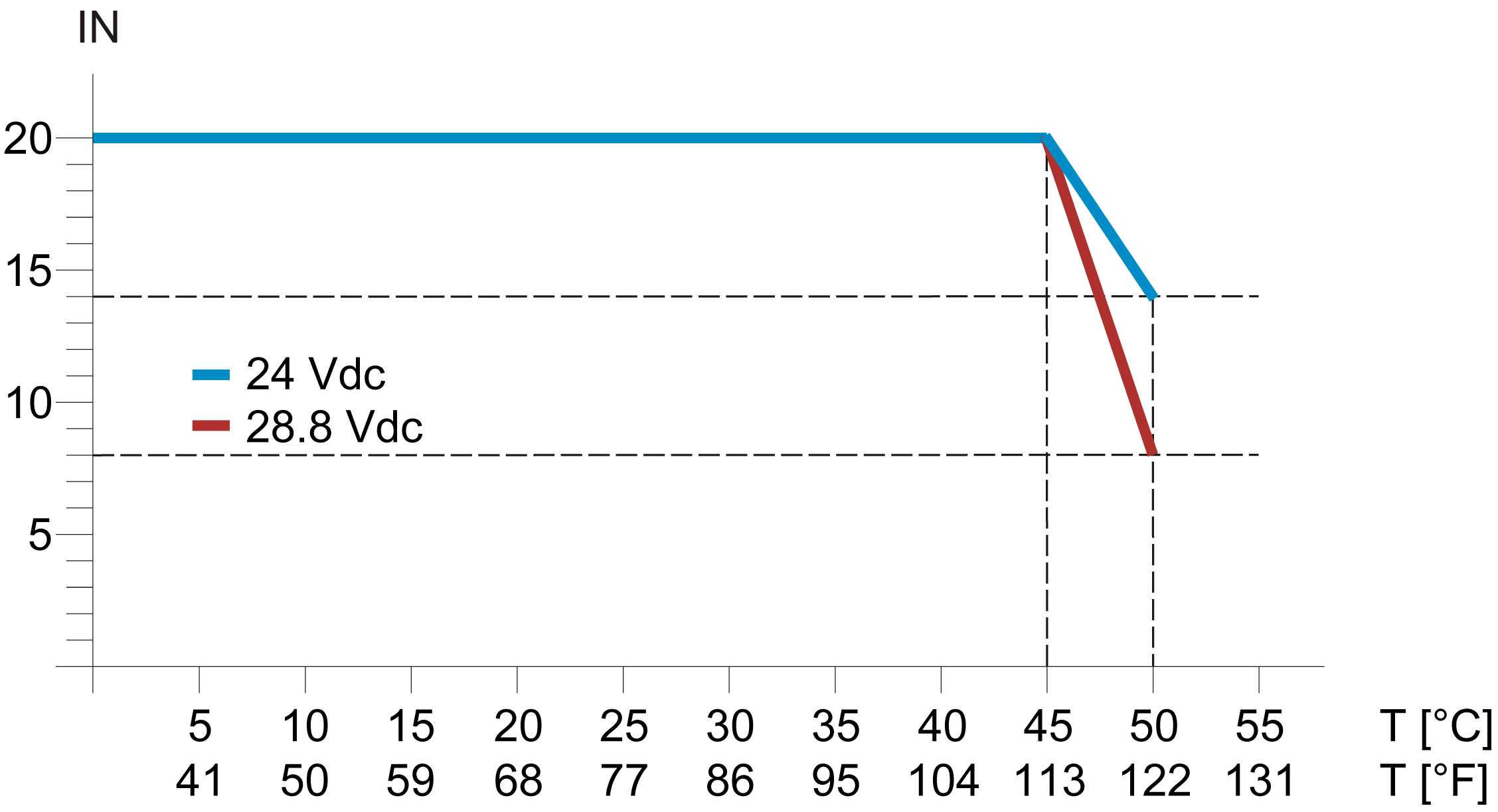
0...+50 °C (+32...122 °F), for derating refer to following table1 |
|
|
Relative humidity |
5...95%, non-condensing |
|
|
Installation at altitudes above sea level: |
0 up to 2000 m (0 up to 6561 ft) |
no derating for altitude |
|
> 2000 m (>6561 ft) |
reduction of ambient temperature by 0.5 °C per 100 m (0.9 °F per 328 ft) |
|
|
EN 60529 protection type |
IP20 |
|
1 Derating in relation to operating temperature and mounting orientation
|
Horizontal installation, 0...+55 °C (+32...131 °F) |
Vertical installation, 0...+50 °C (+32...122 °F) |
|---|---|

|

|
|
IN = number of inputs to be used simultaneously T = temperature |
|
|
NOTE: If a TM5SD000 is installed on the side of the module, the horizontal installation derating is shifted to the right by the following derating bonus:
|
NOTE: Using a TM5SD000 does not provide a derating bonus in vertical installation.
|
Storage and Transport Conditions
The following table lists the storage and transport conditions for the TM5SDI20DFS module:
|
Storage and transport conditions |
|
|---|---|
|
Temperature |
-40...+85 °C (-40...+185 °F) |
|
Relative humidity |
5...95%, non-condensing |
Safety-Related Digital Inputs Characteristics
The following table lists the safety-related digital input characteristics of the TM5SDI20DFS module:
|
Digital input |
||
|---|---|---|
|
Number of input channels |
20 |
|
|
Rated voltage |
24 Vdc |
|
|
Input filter |
hardware |
≤150 µs |
|
software |
default: 0 ms, configurable 0...500 ms |
|
|
Input circuit |
sink |
|
|
Input voltage range |
20.4...28.8 Vdc |
|
|
Input current at 24 Vdc |
maximum 3.28 mA |
|
|
Input resistance |
minimum 7.33 kΩ |
|
|
OFF state (switching threshold low) |
<5 Vdc |
|
|
ON state (switching threshold high) |
>15 Vdc |
|
|
Isolation voltage between channel and bus1) |
See note. |
|
|
Error detection time |
200 ms |
|
NOTE (1) The isolation of the electronic module is 500 Vac RMS between the electronics power by the TM5 bus and those powered by 24 Vdc I/O power segment connected to the module. In practice, the electronic module is installed in the bus base, and there is a bridge between the TM5 power bus and the 24 Vdc I/O power segment. The two power circuits reference the same functional ground (FE) through specific components designed to reduce effects of electromagnetic interference. These components are rated at 30 Vdc or 60 Vdc. This effectively reduces isolation of the entire system from the 500 Vac RMS.
Digital Test (Pulse) Output Characteristics
The following table lists the digital test (pulse) output characteristics of the TM5SDI20DFS module:
|
Digital test outputs |
|
|---|---|
|
Design |
push-pull |
|
Switching voltage |
24 Vdc (-15% / +20%); |
|
Rated output current |
50 mA |
|
Total current |
200 mA |
|
Output protection |
disable individual channels if overcurrent or short circuit occurs |
|
Leakage current when switched off |
0.1 mA |
|
Residual voltage |
0.3 Vdc |
|
Short circuit peak current |
25 A for 15 µs |
|
Short-circuit current |
100 mAeff |
|
Diagnostics status |
output monitoring |
|
Maximum cable length between pulse output and input |
|
Safety-Related Characteristics
The following table lists the safety-related characteristics of the TM5SDI20DFS module:
|
Criteria |
Characteristic value |
|---|---|
|
Maximum performance level according to EN ISO 13849-1 |
PL e |
|
Category according to EN ISO 13849-1 |
CAT 3 when using individual input channels CAT 4 when using input channel pairs (for example SI1 and SI2) or more |
|
Maximum safety integrity level according to EN IEC 62061 |
SIL 3 |
|
Maximum safety integrity level according to EN IEC 61508 |
SIL 3 |
|
Maximum safety integrity level according to EN IEC 61511 |
SIL 3 |
|
PFH |
<1*10-10 |
|
PFD |
|
|
PT |
20 years |
|
DC |
>94% |
|
SFF |
>90% |
|
MTTFd |
2500 years |
|
Maximum 20 years |