Using FC_SercosSetUserRealTimeControlBits
Identification Number (IDN)
A Sercos command is addressed via the identification number (IDN). The IDN has a 32-bit value.
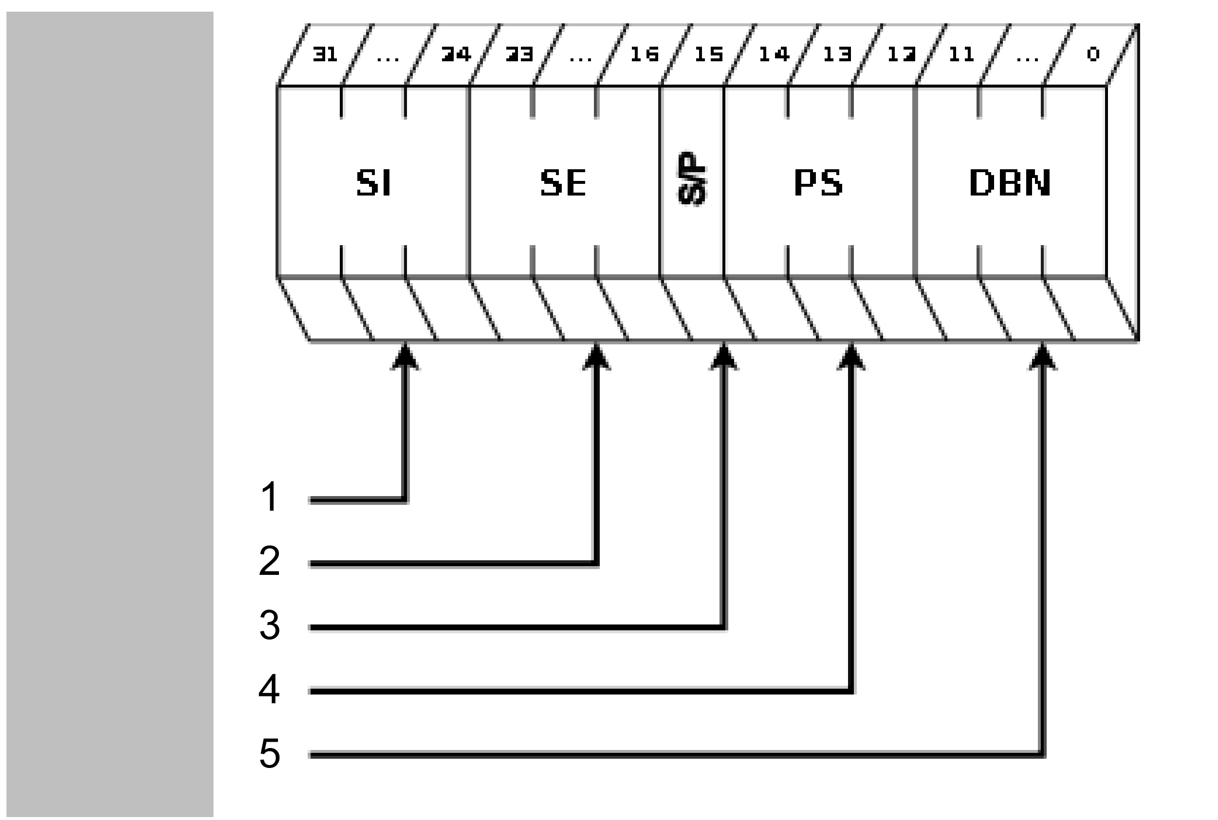
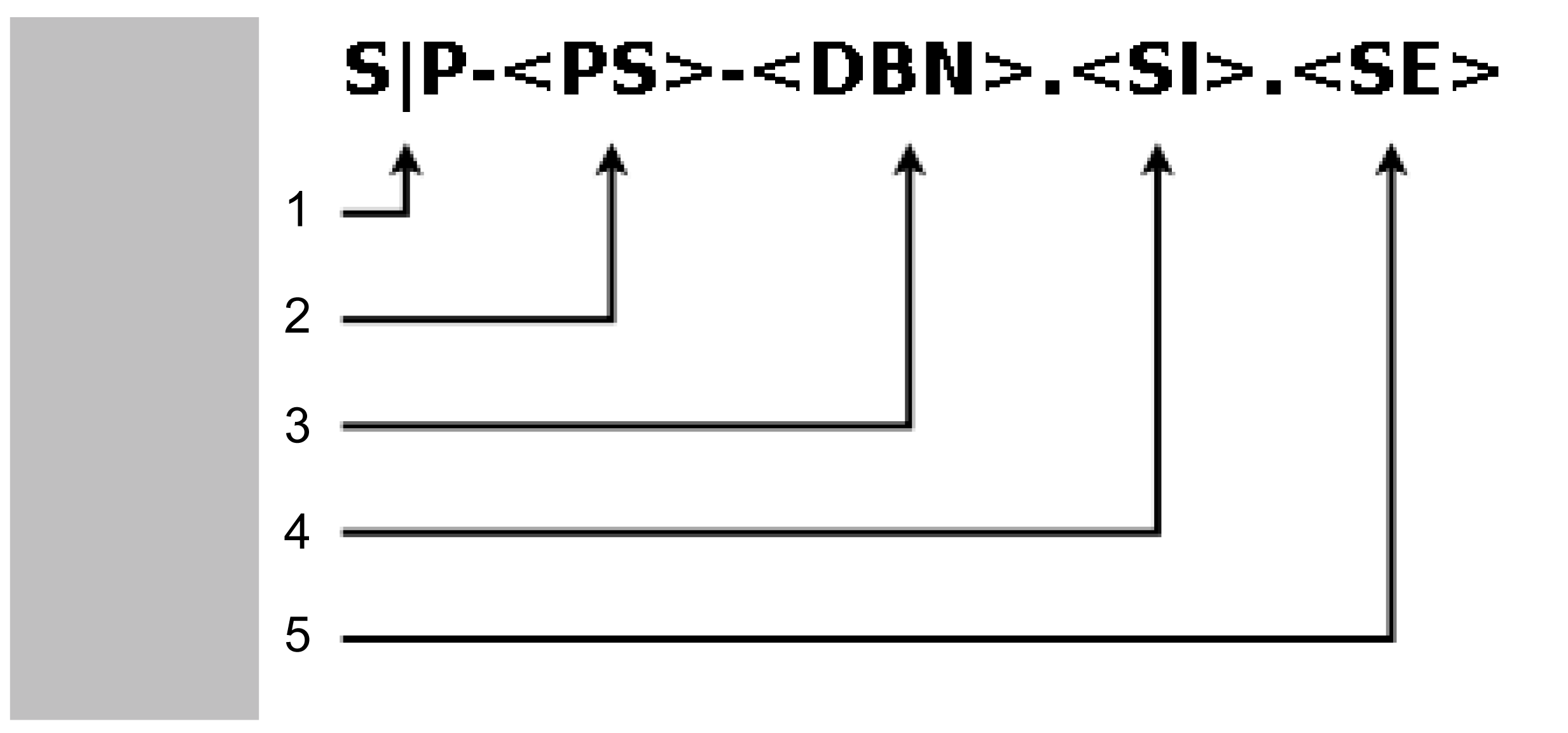
The following figures describe the structure and notation of the IDN.
Structure IDN

1 Structure instance (SI)
2 Structure element (SE)
3 S/P parameter (0:=S; 1:=P)
4 Parameter set (PS)
5 Data block number (DBN)
Notation IDN

1 S/P parameter (SP)
2 Parameter set (PS)
3 Data block number (DBN)
4 Structure instance (SI)
5 Structure element (SE)
The IDN for DC_BusVoltage (P-Parameter) is for example S-0-0380.0.0.
Bit Types
Within a Sercos command the following bit types are used:
-
Functional bit type
-
Reserved bit type
-
Internal bit type
|
Bit type |
Description |
|---|---|
|
Functional bit type |
Functional bits can be written and read. Via functional bits a certain function can be performed on a Sercos device, for example setting the motor brake. |
|
Reserved bit type |
Reserved bits are reserved for the future use. |
|
Internal bit type |
Internal bits can be read but not written. These bits are reserved for the internal use. |
Example
The real-time bits described in the following list are contained in the Sercos IDN P-0-0409.0.0 (in hexadecimal notation: 16#0008199).
Only the functional bits 7, 9, 10, 11 and 13 can be written and read. Other bits are internal bits that only can be read.
|
Bit no. |
Description |
|---|---|
|
15 |
Value from OUT_1 only Lexium LXM52 Drive and Lexium LXM62 Drive) |
|
14 |
Value from OUT_0 (only Lexium LXM52 Drive and Lexium LXM62 Drive) |
|
13 |
Configurable real-time bit #1 Standard configuration: Real-time control brake 0 = Brake closed 1 = Brake released To use this bit, the parameter BrakeMode must be set to "Control brake via user program / 3". If the parameter BrakeMode is set to another value, the brake is not controlled by bit 13. |
|
12 |
Speed-torque-characteristic curve (SpeedTorqueCurve) 0 = Deactivating the speed-torque-characteristic curve 1 = Activating the speed-torque-characteristic curve |
|
11 |
Configurable real-time bit #2 |
|
10 |
Configurable real-time bit #3 |
|
9 |
Configurable real-time bit #4 |
|
8 |
ACTIVE_PS 0 = Power supply is deactivated. 1 = Power supply is activated. |
|
7 |
Configurable real-time bit #5 |
|
6 |
Moment of inertia-feed forward mode 0 = Moment of inertia-feed forward = Motor moment of inertia + J_Gear + J_Load (Default) 1 = Moment of inertia-feed forward = Motor moment of inertia + J_Gear |
|
5 |
Current feed forward (User) 0 = Current feed forward (User) deactivated. 1 = Current feed forward (User) activated. |
|
4 |
Current feed forward 0 = Current feed forward deactivated. 1 = Current feed forward activated (Default) |
|
3 |
OverloadDetectionQuit 0->1 = Acknowledging the overload reaction (low -> high) |
|
2 |
OverloadDetectionOn 0 = Overload detection is deactivated. 1 = Overload detection for FeedbackCurrent is active. |
|
1 |
UserCurrentOn 0 = Current on DrivePeakCurrent is limited. 1 = Current on UserCurrent is limited. |
|
0 |
AccelerationOverflow 0 = The acceleration is inside the defined range. 1 = The acceleration exceeds the defined range. |
Example
The following example explains how to release the brakes. Therefore a mask is defined which allows access to the configurable bits. Furthermore the value to release the brakes is defined.
Declaration
PROGR AM SR_Demo
VAR
   xOnce : BOOL := TRUE;
   diResult : DINT := -99;
   dwMask : DWORD := 16#00000000;
   dwIDN : DWORD := 16#00000000;
   dwValue : DWORD := 16#00000000;
END_VAR
Program
IF xOnce = TRUE THEN
xOnce := FALSE;
   dwMask := 16#00002E80;  (* Only the configurable bits 7, 9, 10, 11 and 13 are accessible *)
   dwIDN := 16#00008199;  (* IDN for P-0-0409.0.0 *)
   dwValue:= 16#00002000;  (* bit 13 = TRUE, value to relase the brakes *)
   diResult := FC_SercosSetUserRealTimeControlBits(
      i_stLogAddr := DRV_Lexium62.stLogicalAddress,
      i_dwMask := dwMask,
      i_dwIDN := dwIDN,
      iq_dwValue := dwValue);
END_IF