Cabling the VRKP•S0•WD
Preparing the Cable Connections
|
Step |
Action |
|---|---|
|
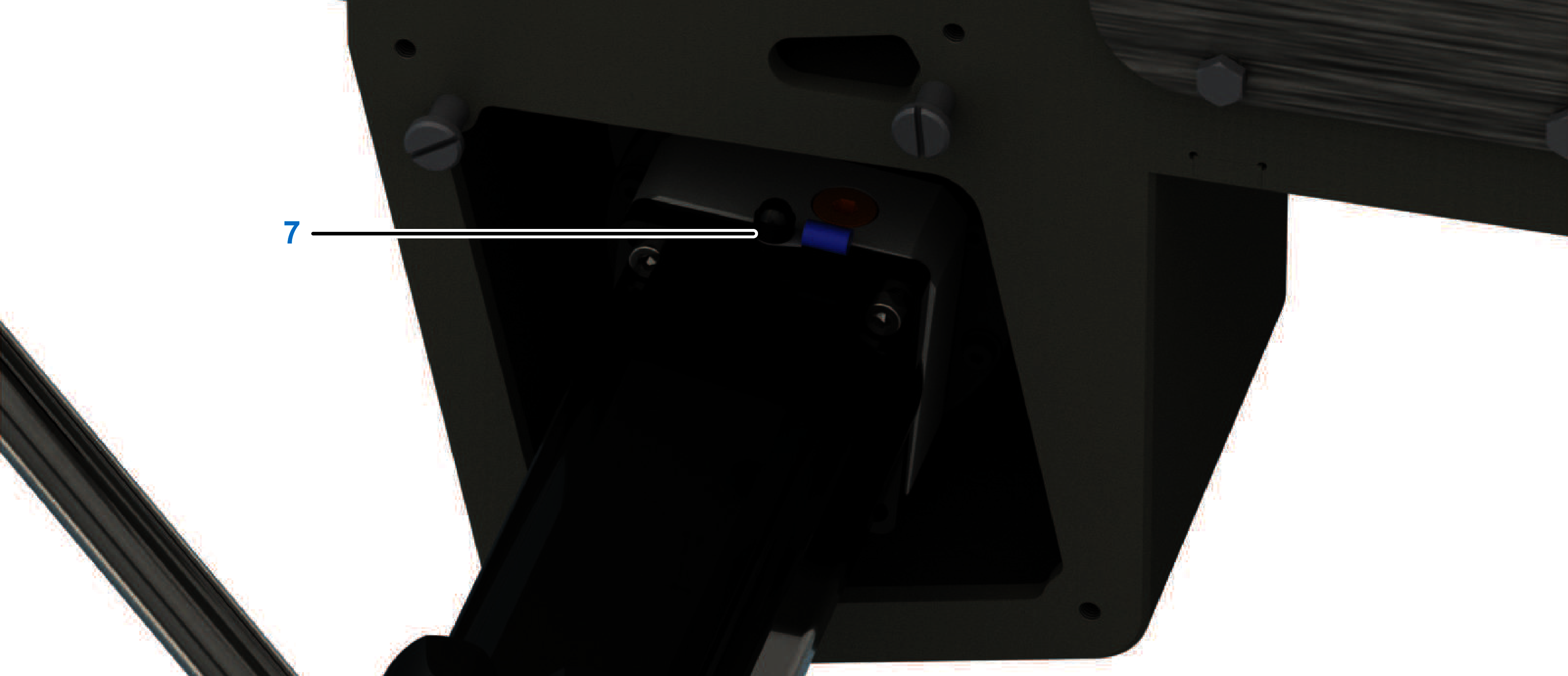
1 |
Remove the five screws and washers (5) from the media cover (7). 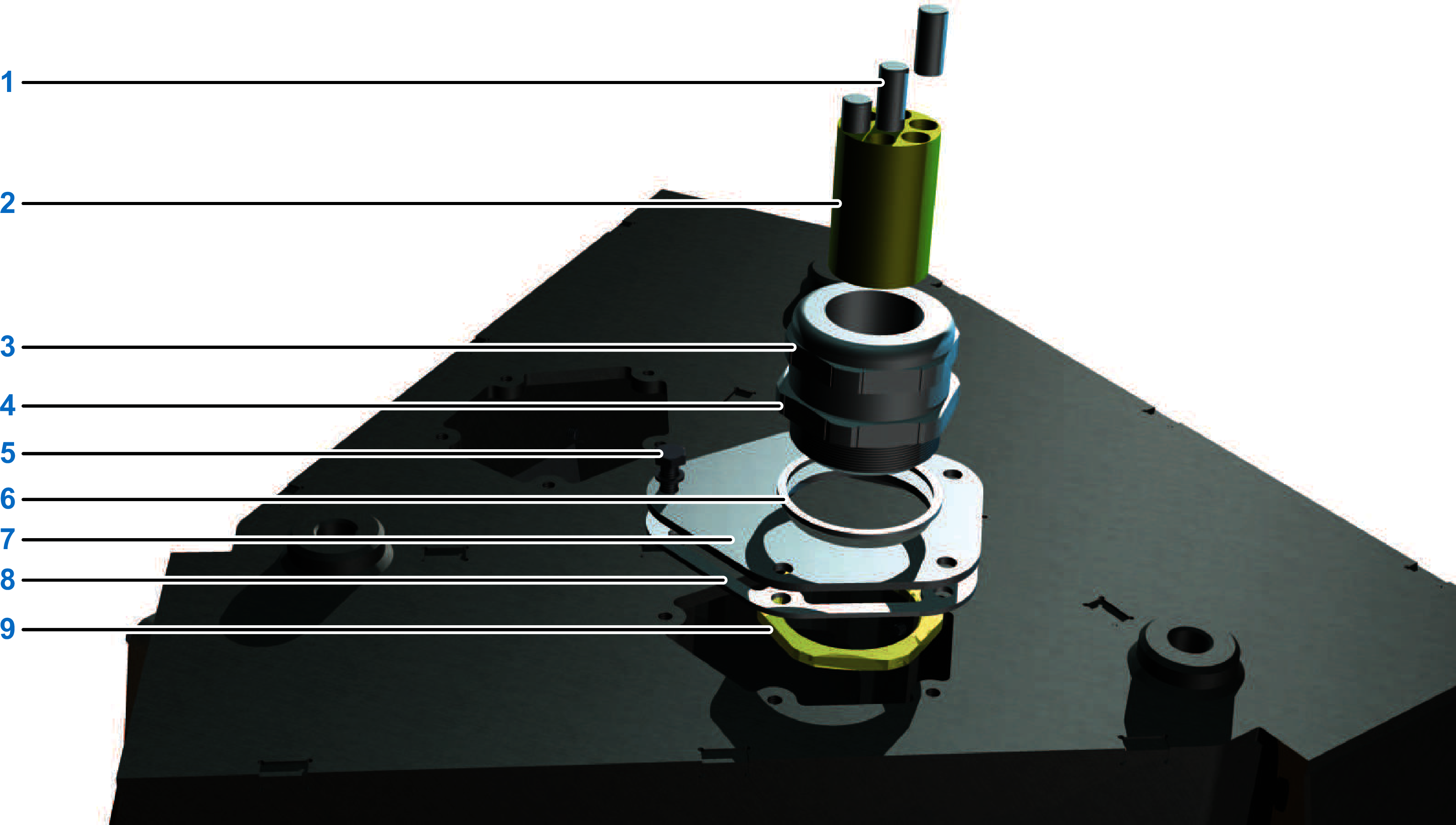
|
|
2 |
Remove the media cover with the mounted M50 cable connections and the media cover sealing gasket (8). |
|
3 |
Dismount the two M50 cable connections:
|
|
4 |
Remove the sealing inserts (2) from the cable glands of the M50 cable connections. |
|
5 |
Laterally slit each sealing insert in accordance with the respective number of cables to be routed. |
|
6 |
Feed the three encoder cables (four with VRKP•••R) first through the top half of the M50 cable connection and next through the insert with the smaller apertures (10). 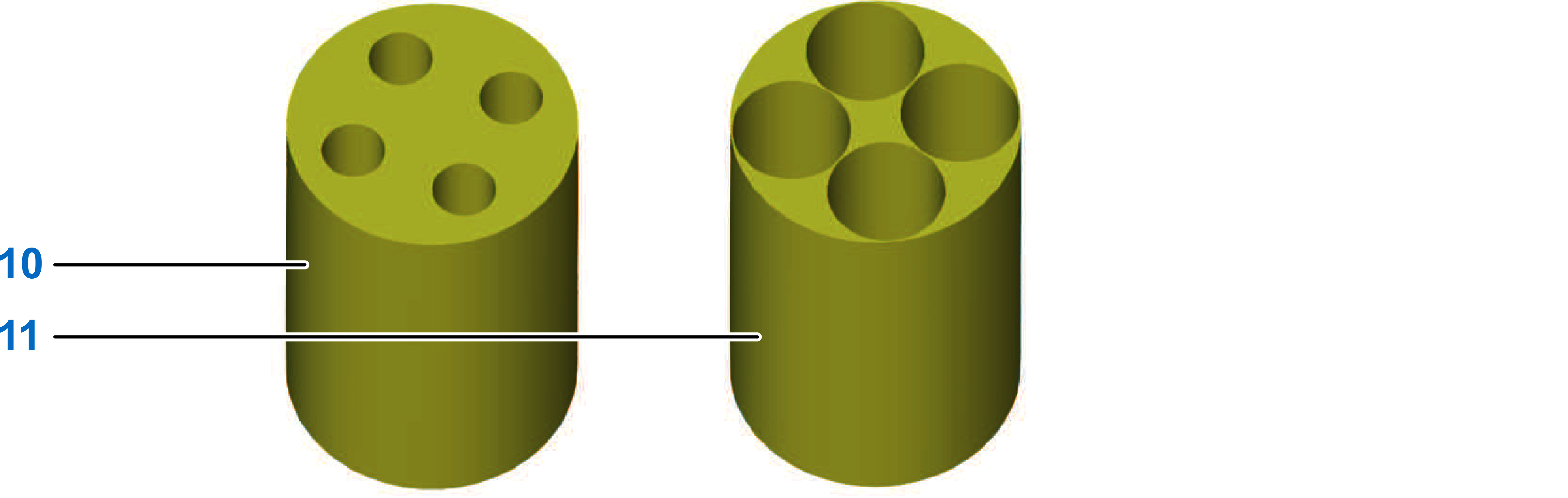
|
|
7 |
Feed the three power cables (four with VRKP•••R) first through the top half of the M50 cable connection and next through the insert with the larger apertures (11). |
|
8 |
Close any not required gland of the insert with a sealing plug (1). |
|
9 |
Feed the cables through the lower half of the M50 cable connections and insert the sealing inserts into them. |
|
10 |
Close the two halves of each M50 cable gland. Tightening torque: 15 Nm (133 lbf-in) |
Connecting the Components of the Robot
|
Step |
Action |
|---|---|
|
1 |
Insert the sealing ring (2) between the M50 cable connection (1) and the media covers (3) and fasten the M50 cable connection to the media cover with the locknut (5). Tightening torque: 15 Nm (133 lbf-in) 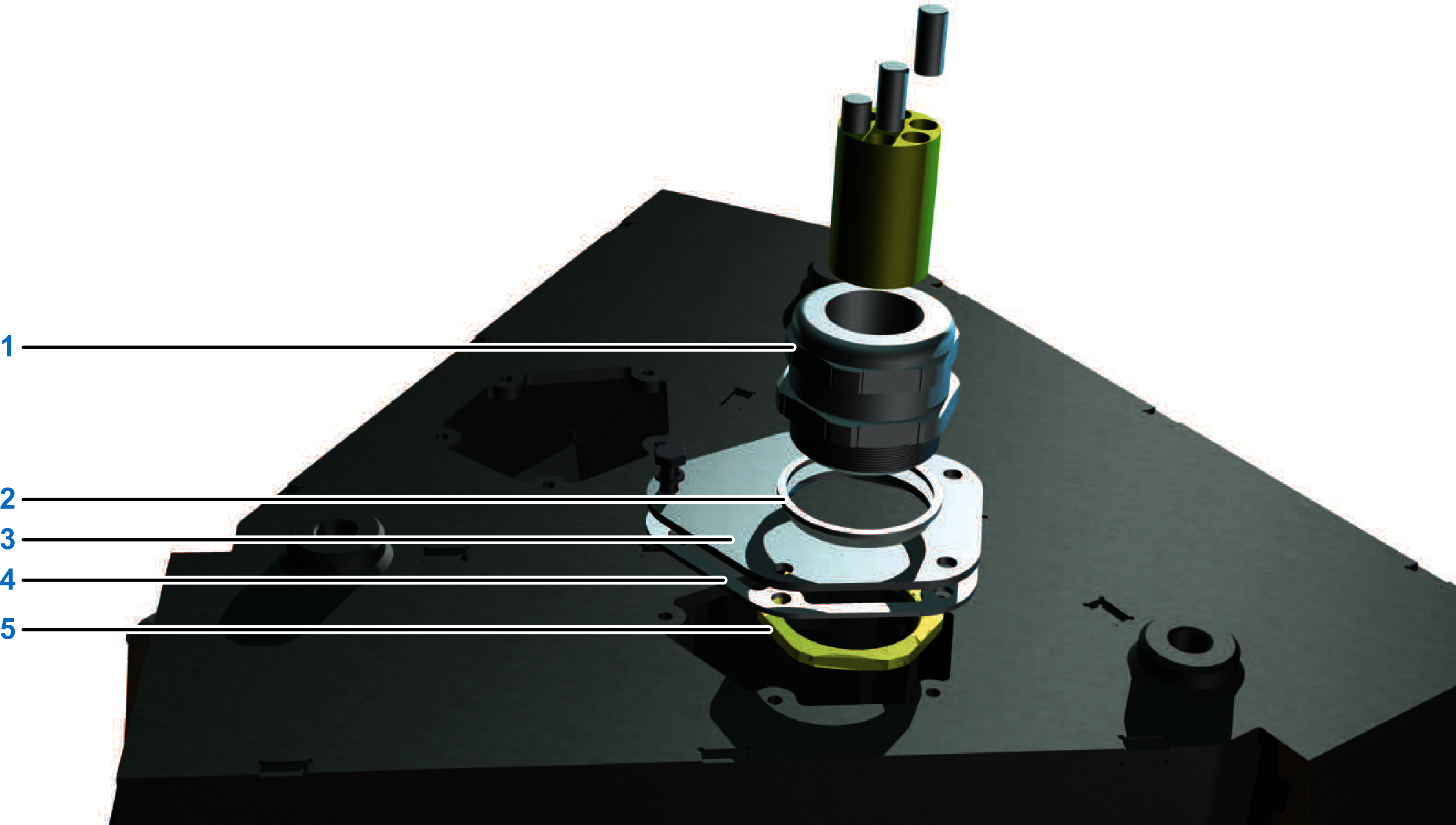
|
|
2 |
Feed the ground cables (protective earth ground) through the top half of the M16 cable connection and next through the sealing insert. |
|
3 |
Only for VRKP2S0•WD: Feed the cable for fan connection (+24 Vdc supply) through the top half of the second M16 cable connection and next through the sealing insert. |
|
4 |
Fasten the M16 cable connection to the media cover the same way as the M50 cable connection. Tightening torque: 6 Nm (53 lbf-in) |
|
5 |
Feed the encoder cables, the power cables, and the ground cables (protective earth ground) through the media cover sealing gasket (4) and insert them into the opening of the robot housing.
NOTE: For equipment that you are supplying that is not described in the present document, consult the documentation for those products.
|
|
6 |
Feed the encoder and the power cables to the motors. |
|
7 |
Attach the encoder and the power cables as described in the SH3 Servo Motor User Guide. |
|
8 |
Fasten each of the media covers including the media cover sealing gasket with the five screws and washers (6). Tightening torque: 6 Nm (53 lbf-in) 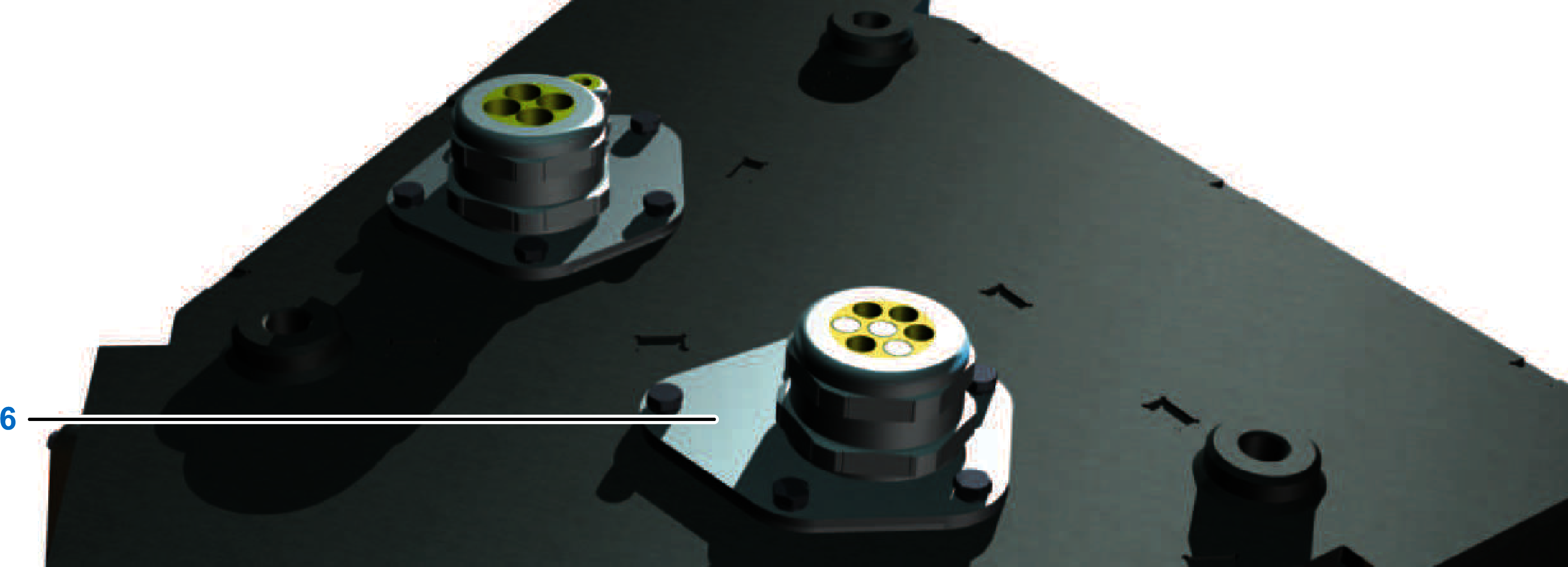
|
|
9 |
Couple the DC buses of the servo amplifiers so that braking motors can feed back their power to the accelerating motors in the case of an on-path stop of the robot. Due to the coupling of the DC buses, the existing energy suffices in many cases for an on-path stop of the robot. In case of a power interruption of the 24 Vdc supply this backfeeding measure does not have any effect. For more information, see Lexium 52 Hardware Guide or Lexium 62 Hardware Guide.
NOTE: When routing the cables, ensure that the grounding cap (7) remains on the ground connection of the motors. The motor supply cable may become damaged by the thread of the ground strap attachment.
|
|
10 |
Verify the correct routing and fastening of the cables. |
| DANGER | |
|---|---|
| DANGER | |
|---|---|
| NOTICE | |
|---|---|
| NOTICE | |
|---|---|
Cabling the Fans (Only for VRKP2S0•WD)
|
Step |
Action |
|---|---|
|
1 |
Feed the cable for fan connection (+24 Vdc supply) to the terminal strip (1) inside the housing. 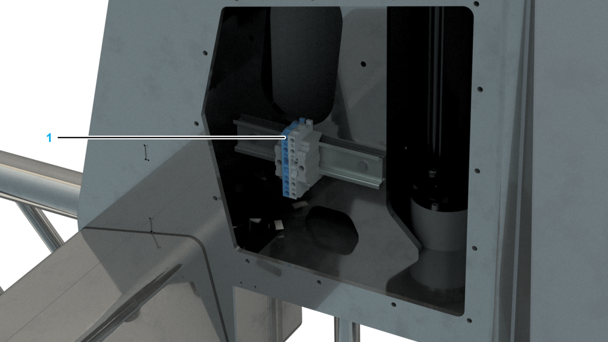
|
|
2 |
Connect the 0 Vdc conductor to the blue multiple terminal. |
|
3 |
Connect the +24 Vdc line to the gray multiple terminal.
NOTE: For the distribution of the +24 Vdc supply for further customer-specific installations, use the following Schneider Electric accessories:
|
|
4 |
Verify the correct routing and fastening of the cables. |
|
5 |
Verify that the fans take air from the central area of the housing and blow this air to the motor cover area. |
| DANGER | |
|---|---|