Indicators of the Segments
Overview
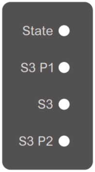
The Lexium™ MC12 long stator motor segments are equipped with four LED indicators on the top:
|
State: Segment state |
|
S3 P1: Port status Sercos bus |
|
|
S3: Network status Sercos bus |
|
|
S3 P2: Port status Sercos bus |
State LED Indicator
The State LED indicates the internal state of the segment.
|
LED indicator color / status |
Flashing pattern (3 seconds) |
Description |
Instructions / information for the user |
|---|---|---|---|
|
Off |
– |
Device is not energized or is otherwise inoperable. |
|
|
Steady orange |

|
Segment boot phase |
Boot and initialization phase of the segment |
|
Flashing green (4 Hz, 125 ms) |

|
Segment update state |
Firmware update file transfer or internal firmware update process. |
|
Flashing slowly orange (1 Hz, 500 ms) |

|
SFO not supplied with 24 Vdc, power stage not prepared. |
– |
|
Flashing slowly green (1 Hz, 500 ms) |

|
SFO supplied with 24 Vdc, power stage not prepared. |
– |
|
Orange for 875 ms, off for 125 ms |

|
SFO not supplied with 24 Vdc, power stage prepared. |
– |
|
Green for 875 ms, off for 125 ms |

|
SFO supplied with 24 Vdc, power stage prepared. |
– |
|
Steady green |

|
Power stage active |
– |
|
Flashing red (4 Hz, 125 ms) |

|
A general error has been detected. |
|
|
Steady red |

|
A non-recoverable error has been detected requiring user intervention:
|
|
S3 P1 and S3 P2 LED Indicators
The S3 P1 and S3 P2 LEDs indicate the status of both Sercos ports.
|
LED indicator color / status |
Flashing pattern (3 seconds) |
Description |
Instructions / information for the user |
|---|---|---|---|
|
Off |
– |
Possible causes:
|
|
|
Steady orange |
|
Cable connected, no Sercos communication |
– |
|
Steady green |
|
Cable connected, active Sercos communication |
– |
S3 LED Indicator
The S3 LED indicates the network status of the Sercos bus.
|
LED indicator color / status |
Flashing pattern (3 seconds) |
Description |
Instructions / information for the user |
|---|---|---|---|
|
Off |
– |
Possible causes:
|
|
|
Steady green |
|
Active Sercos connection without an error detected in the CP4. |
– |
|
Flashing green (2 Hz, 250 ms) |

|
The device is in loopback mode. Loopback describes the situation in which the Sercos telegrams have to be sent back on the same port on which they were received. Possible cause: Sercos loop break |
Workaround:
Reset condition:
NOTE: If during phase CP1 a line topology or ring break was detected (device in loopback mode), the LED indicator condition does not change.
|
|
Steady red |
|
Sercos diagnostic class 1 (C1D) error has been detected on port 1 and/or port 2. |
Reset condition:
|
|
Flashing red / green (2 Hz, 250 ms) |

|
Communication error has been detected. Possible causes:
|
Reset condition:
|
|
Orange |
|
The device is in a communications phase CP0 up to and including CP3 or HP0 up to and including HP2. Sercos telegrams are received. |
See table below for the individual CP indications. |
|
Flashing orange (2 Hz, 250 ms) |

|
Device identification |
– |
|
LED indicator color / status |
Flashing pattern (3 seconds) |
Description |
Instructions / information for the user |
|---|---|---|---|
|
Steady orange |
|
Communication phase is CP0 |
– |
|
One brief green flash followed by steady orange |

|
Communication phase is CP1 |
– |
|
Two brief green flashes followed by steady orange |

|
Communication phase is CP2 |
– |
|
Three brief green flashes followed by steady orange |

|
Communication phase is CP3 |
– |