Conveyor View
Overview
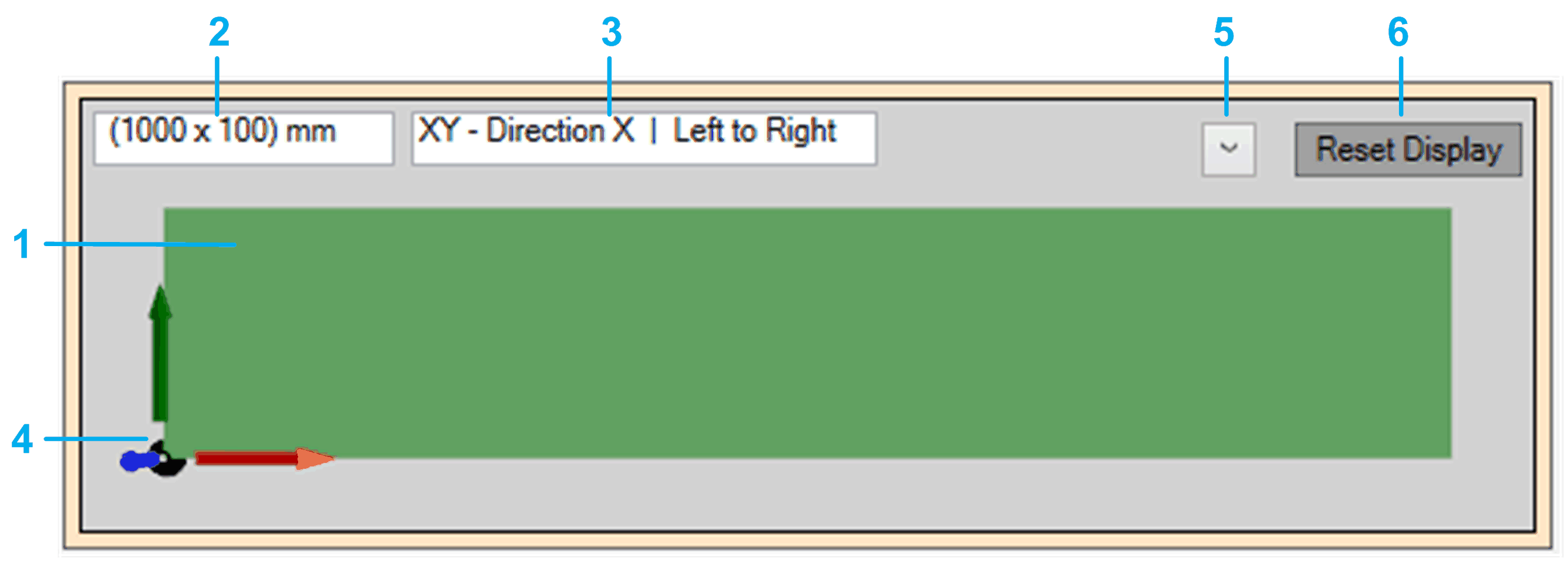
The conveyor view displays the conveyor as a 3D graphic object.
Targets added via the property stTargets are displayed on the conveyor.
You can modify the display settings (5) of the conveyor view and the position and the viewing direction of the observer (camera) towards the conveyor (by mouse operations).
Conveyor view (default)

The default view (top down) shows the following items:
|
Item |
Description |
|---|---|
|
|
Representation of the conveyor. |
|
|
You can modify the and the (, , , , ) in the tab. |
|
|
|
|
|
Origin and coordinate axes of the conveyor representation. |
|
|
Display options:
The activation/deactivation of an option becomes effective after the options menu is left. By default, the options , , and are activated. |
|
|
button If the conveyor has been moved and is not visible in the conveyor view, click the to set the conveyor view to the default settings. |
Mouse Operations
The position and the viewing direction of the observer (camera) towards the conveyor can be modified by mouse operations:
-
Click and hold the left mouse button to pan the view (horizontal and vertical movement).
-
Click and hold the right mouse button to rotate the view (longitudinal axis rotation).
-
Use the mouse wheel to zoom the view(zooming in and out).