Connection Details Controller
CN1 - Control Voltage And Watchdog
Connection CN1
|
Pin |
Designation |
Meaning |
Range |
|---|---|---|---|
|
1 |
DC +24 V |
Supply voltage |
-15 % / +25 % |
|
2 |
DC 0 V |
Supply voltage |
– |
|
3 |
+UL |
For digital outputs |
DC +24 V -15 % / +25 % |
|
4 |
L0 |
For digital inputs / outputs |
– |
|
5 |
DC +24 V |
Supply voltage (bridged with pin 1, maximum ampacity 4 A) |
– |
|
6 |
DC 0 V |
Supply voltage (bridged with pin 2, maximum ampacity 4 A) |
– |
|
7 |
WD |
Watchdog relay |
– |
|
8 |
WD |
Watchdog relay |
– |
Input connection
1 Internal wiring diagram - input connection of power supply (simplified)
2 Internal supply voltage
3 Supply voltage for digital outputs/inputs
CN2 - Digital Outputs
Connection CN2
|
Pin |
Designation |
Meaning |
|---|---|---|
|
1 |
DQ_0 |
Digital output 0 |
|
2 |
DQ_1 |
Digital output 1 |
|
3 |
DQ_2 |
Digital output 2 |
|
4 |
DQ_3 |
Digital output 3 |
|
5 |
DQ_4 |
Digital output 4 |
|
6 |
DQ_5 |
Digital output 5 |
|
7 |
DQ_6 |
Digital output 6 |
|
8 |
DQ_7 |
Digital output 7 |
|
9 |
DQ_8 |
Digital output 8 |
|
10 |
DQ_9 |
Digital output 9 |
|
11 |
DQ_10 |
Digital output 10 |
|
12 |
DQ_11 |
Digital output 11 |
|
13 |
DQ_12 |
Digital output 12 |
|
14 |
DQ_13 |
Digital output 13 |
|
15 |
DQ_14 |
Digital output 14 |
|
16 |
DQ_15 |
Digital output 15 |
CN3 - Digital Inputs
Connection CN3
|
Pin |
Designation |
Meaning |
|---|---|---|
|
1 |
DI_0 |
Digital input 0 |
|
2 |
DI_1 |
Digital input 1 |
|
3 |
DI_2 |
Digital input 2 |
|
4 |
DI_3 |
Digital input 3 |
|
5 |
DI_4 |
Digital input 4 |
|
6 |
DI_5 |
Digital input 5 |
|
7 |
DI_6 |
Digital input 6 |
|
8 |
DI_7 |
Digital input 7 |
|
9 |
DI_8 |
Digital input 8 |
|
10 |
DI_9 |
Digital input 9 |
|
11 |
DI_10 |
Digital input 10 |
|
12 |
DI_11 |
Digital input 11 |
|
13 |
DI_12 |
Digital input 12 |
|
14 |
DI_13 |
Digital input 13 |
|
15 |
DI_14 |
Digital input 14 |
|
16 |
DI_15 |
Digital input 15 |
|
17 |
DI_16 |
Digital input 16 |
|
18 |
DI_17 |
Digital input 17 |
|
19 |
DI_18 |
Digital input 18 |
|
20 |
DI_19 |
Digital input 19 |
CN4 - Touchprobe And Fast Digital Inputs
Connection CN4
|
Pin |
Designation |
Meaning |
|---|---|---|
|
1 |
T.0 |
Touchprobe input 0 |
|
2 |
T.1 |
Touchprobe input 1 |
|
3 |
T.2 |
Touchprobe input 2 |
|
4 |
T.3 |
Touchprobe input 3 |
|
5 |
T.4 |
Touchprobe input 4 |
|
6 |
T.5 |
Touchprobe input 5 |
|
7 |
T.6 |
Touchprobe input 6 |
|
8 |
T.7 |
Touchprobe input 7 |
|
9 |
T.8 |
Touchprobe input 8 |
|
10 |
T.9 |
Touchprobe input 9 |
|
11 |
T.10 |
Touchprobe input 10 |
|
12 |
T.11 |
Touchprobe input 11 |
|
13 |
T.12 |
Touchprobe input 12 |
|
14 |
T.13 |
Touchprobe input 13 |
|
15 |
T.14 |
Touchprobe input 14 |
|
16 |
T.15 |
Touchprobe input 15 |
|
17 |
F.0 |
Fast input 1 |
|
18 |
F.1 |
Fast input 2 |
|
19 |
F.2 |
Fast input 3 |
|
20 |
F.3 |
Fast input 4 |
CN5 - Analog Inputs / Outputs
Connection CN5
|
Pin |
Designation |
Meaning |
Range |
||||
|---|---|---|---|---|---|---|---|
|
1 |
AI_0 + |
Analog input 0+ |
-10...+10 V (*) 0...20 mA (**) |
||||
|
2 |
J_0 + |
Br. current input 0 + |
– |
||||
|
3 |
AI_0 - |
Analog input 0- |
– |
||||
|
4 |
A_GND 0 |
Analog ground 0 |
– |
||||
|
5 |
12 V Out 0 |
Output voltage 0 |
12 V |
||||
|
6 |
FE (functional earth) |
Shield |
– |
||||
|
7 |
AO_0 |
Analog output 0 |
-10...+10 V |
||||
|
8 |
A_GND AO_0 |
Analog ground 0 |
– |
||||
|
9 |
FE (functional earth) |
Shield |
– |
||||
|
10 |
AI_1 + |
Analog input 1+ |
-10...+10 V (*) 0...20 mA (**) |
||||
|
11 |
J_1 + |
Br. current input 1 + |
– |
||||
|
12 |
AI_1 - |
Analog input 1- |
– |
||||
|
13 |
A_GND 1 |
Analog ground |
– |
||||
|
14 |
12 V Out 1 |
Output voltage 1 |
12 V |
||||
|
15 |
FE (functional earth) |
Shield |
– |
||||
|
16 |
AO_1 |
Analog output 1 |
-10...+10 V |
||||
|
17 |
A_GND AO_1 |
Analog ground |
– |
||||
|
18 |
FE (functional earth) |
Shield |
– |
||||
|
|||||||
Input / Output connection
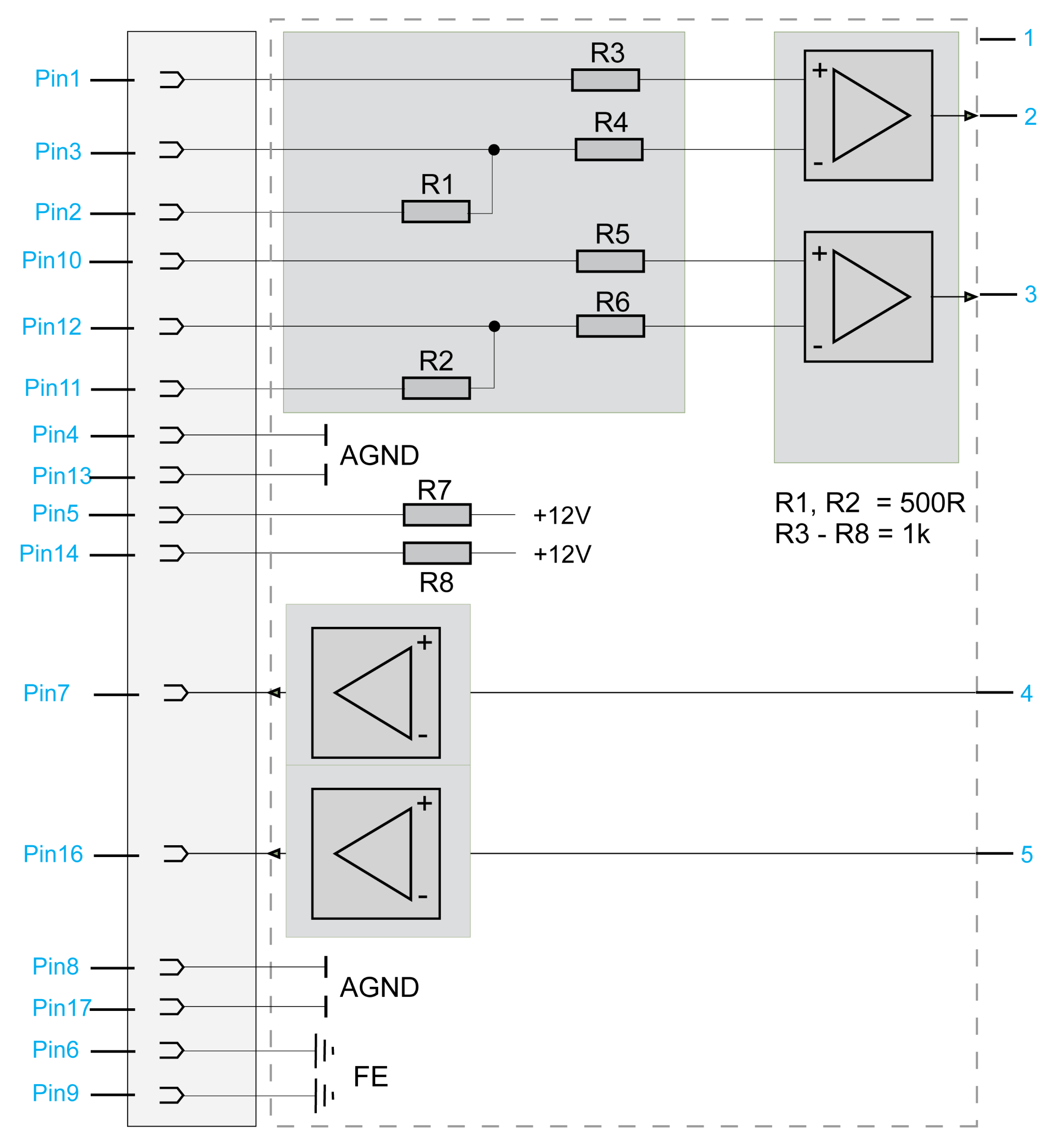
1 Internal wiring diagram (simplified)
2 Analog input 1
3 Analog input 2
4 Analog output 1
5 Analog output 2
CN7 - USB Host
Connection CN7
|
Pin |
Designation |
Meaning |
Range |
|---|---|---|---|
|
1 |
VBUS / +5V |
– |
– |
|
2 |
D- / Data- |
– |
– |
|
3 |
D+ / Data+ |
– |
– |
|
4 |
GND / Ground |
– |
– |
CN8 - Ethernet
Connection CN8 of PacDrive LMC Pro
|
Pin |
Designation |
Meaning |
Function |
|---|---|---|---|
|
1 |
Tx+ |
Output transmit data + |
– |
|
2 |
Tx- |
Output transmit data - |
– |
|
3 |
Rx+ |
Input receive data + |
– |
|
4 |
– |
Reserved |
– |
|
5 |
– |
Reserved |
– |
|
6 |
Rx- |
Input receive data - |
– |
|
7 |
– |
Reserved |
– |
|
8 |
– |
Reserved |
– |
Connection CN8 of PacDrive LMC Pro2
|
Pin |
Designation |
Meaning |
Function |
|---|---|---|---|
|
1 |
MDI 0+ |
Transmit line 0 |
– |
|
2 |
MDI 0- |
Transmit line 0 |
– |
|
3 |
MDI 1+ |
Transmit line 1 |
– |
|
4 |
MDI 2+ |
Transmit line 2 |
– |
|
5 |
MDI 2- |
Transmit line 2 |
– |
|
6 |
MDI 1- |
Transmit line 1 |
– |
|
7 |
MDI 3+ |
Transmit line 3 |
– |
|
8 |
MDI 3- |
Transmit line 3 |
– |
There are two LED indicators affixed to the Ethernet connection.
For further information on the functions of the LED indicators, refer to the description of the Ethernet status LED indicator .
CN9 - PacNet

Connection CN9
|
Pin |
Designation |
Meaning |
Function |
|---|---|---|---|
|
1 |
TxD+ |
Output transmit data + |
– |
|
2 |
TxD- |
Output transmit data - |
– |
|
3 |
RxD+ |
Input receive data + |
– |
|
4 |
TxC- |
Output transmit clock - |
– |
|
5 |
TxC+ |
Output transmit clock + |
– |
|
6 |
RxD- |
Input receive data - |
– |
|
7 |
RxC+ |
Input receive clock + |
– |
|
8 |
RxC- |
Input receive clock - |
– |
CN10/CN11 - RT Ethernet
Connection CN10/11
|
Pin |
Designation |
Meaning |
Function |
|---|---|---|---|
|
1 |
Tx+ |
Output transmit data + |
– |
|
2 |
Tx- |
Output transmit data - |
– |
|
3 |
Rx+ |
Input receive data + |
– |
|
4 |
– |
Reserved |
– |
|
5 |
– |
Reserved |
– |
|
6 |
Rx- |
Input receive data - |
– |
|
7 |
– |
Reserved |
– |
|
8 |
– |
Reserved |
– |
-
When using the PacDrive LMC Pro/Pro2 as EtherCAT slave, the connection CN10 represents the input port and the connection CN11 the output port. The input port and output port are predetermined by the firmware and cannot be configured.
-
When using the PacDrive LMC Pro/Pro2 as EtherCAT Master, only the connection CN10 can be used.
LED Description for CN10/CN11 - RT Ethernet
For further information on the functions of the LED indicators, refer to the description of the Indicators and Control elements.
LED states valid for SoMachine Motion V4.1(firmware version V1.51.10.6) and earlier (EtherCAT master stack version V3):
LEDs EtherCAT master
|
LED indicator |
Color |
State |
Meaning |
|---|---|---|---|
|
LINK/RJ45 Ch0 & Ch1 |
green LED indicator |
||
|
Green |
On |
A connection to Ethernet exists. |
|
|
Green |
Flashing |
The device sends/receives Ethernet frames. |
|
|
Off |
Off |
The device has no connection to Ethernet. |
|
|
RJ45 Ch0 & Ch1 |
yellow LED indicator |
||
|
– |
– |
The LED indicator is not used. |
|
LEDs EtherCAT slave
|
LED indicator |
Color |
State |
Meaning |
|---|---|---|---|
|
LINK/RJ45 Ch0 & Ch1 |
green LED indicator |
||
|
Green |
On |
A connection to Ethernet exists. |
|
|
Green |
Flashing |
The device sends/receives Ethernet frames. |
|
|
Off |
Off |
The device has no connection to Ethernet. |
|
|
RJ45 Ch0 & Ch1 |
yellow LED indicator |
||
|
– |
– |
The LED indicator is not used. |
|
LED states valid for EcoStruxure Machine Expert V1.0 and later (EtherCAT master stack version V4) and SoMachine Motion V4.2 (firmware version V1.53.9.0) and later (EtherCAT master stack version V4):
LED indicators EtherCAT master
|
LED indicator |
Color |
State |
Meaning |
|---|---|---|---|
|
LINK/RJ45 Ch0 |
green LED indicator |
||
|
Green |
On |
A connection to Ethernet exists. |
|
|
Green |
Flashes |
The device sends / receives Ethernet frames. |
|
|
Off |
Off |
The device has no connection to Ethernet. |
|
|
ACT RJ45 Ch0 |
yellow LED indicator |
||
|
off |
– |
– |
|
LED indicators EtherCAT slave
|
LED indicator |
Color |
State |
Meaning |
|---|---|---|---|
|
LINK/RJ45 Ch0 & CH1 |
green LED indicator |
||
|
Green |
On |
A connection to Ethernet exists. |
|
|
Green |
Flashes |
The device sends / receives Ethernet frames. |
|
|
Off |
Off |
The device has no connection to Ethernet. |
|
|
RJ45 Ch0 & CH1 |
yellow LED indicator |
||
|
– |
– |
– |
|
CN12/CN13 - Sercos
Connection CN12/CN13
|
Pin |
Designation |
Meaning |
Range |
|---|---|---|---|
|
1 |
Tx+ |
Output transmit data + |
– |
|
2 |
Tx- |
Output transmit data - |
– |
|
3 |
Rx+ |
Input receive data + |
– |
|
4 |
– |
Reserved |
– |
|
5 |
– |
Reserved |
– |
|
6 |
Rx- |
Input receive data - |
– |
|
7 |
– |
Reserved |
– |
|
8 |
– |
Reserved |
– |
-
Connect your Sercos device to the PacDrive LMC Pro/Pro2 either completely via Sercos port 1 (CN12) in line topology or in ring topology using Sercos port 1 and 2 (CN12/CN13).
-
Do not connect the Sercos devices to the PacDrive LMC Pro/Pro2 via double line topology (CN12/CN13).
-
Do not connect the Sercos devices to the PacDrive LMC Pro/Pro2 only via Sercos port 2 (CN13).
CN14 - Master Encoder (Hiperface)
The Hiperface connection consists of a standard, differential, digital connection (RS-485 = 2 wires), a differential, analog connection (sine- and cosine signal = 4 wires), and a mains connection to supply the encoder (+9 V, GND = 2 wires).
Connection CN14 - Master encoder (Hiperface)
|
Pin |
Designation |
Meaning |
Range |
|---|---|---|---|
|
1 |
REFSIN |
Reference signal sine |
– |
|
2 |
SIN |
Sinusoidal trace |
– |
|
3 |
REFCOS |
Reference signal cosinus |
– |
|
4 |
COS |
Cosinus trace |
– |
|
5 |
+9 V |
Supply voltage |
– |
|
6 |
RS485- |
Parameter channel - |
– |
|
7 |
RS485+ |
Parameter channel + |
– |
|
8 |
SC_SEL |
Master encoder plugged in (bridge to GND) |
– |
|
9 |
GND |
Supply voltage |
– |
CN14 - Master Encoder (Incremental)
Connection CN14 - Master encoder (incremental)
|
Pin |
Designation |
Meaning |
Range |
|---|---|---|---|
|
1 |
_UA |
Track A |
– |
|
2 |
UA |
Track A |
– |
|
3 |
_UB |
Track B |
– |
|
4 |
UB |
Track B |
– |
|
5 |
+5 V |
Supply voltage |
– |
|
6 |
_UO |
Track O |
– |
|
7 |
UO |
Track O |
– |
|
8 |
– |
Reserved |
– |
|
9 |
GND |
Ground |
– |
CN15 - COM 1 (RS-232)
Connection CN15
|
Pin |
Designation |
Meaning |
Range |
|---|---|---|---|
|
1 |
DCD |
Data carrier detect |
– |
|
2 |
RxD |
Receive data |
– |
|
3 |
TxD |
Transmit data |
– |
|
4 |
DTR |
Data terminal ready |
– |
|
5 |
GND |
Signal ground |
– |
|
6 |
DSR |
Data set ready clear to send |
– |
|
7 |
RTS |
Request to send |
– |
|
8 |
CTS |
Clear to send |
– |
|
9 |
RI |
Ring indicator |
– |
CN16 - COM 2 (RS-485)
Connection CN16
|
Pin |
Designation |
Meaning |
Range |
|---|---|---|---|
|
1 |
+5 VM |
Supply voltage |
– |
|
2 |
TxD- |
RS-485 transmit- |
– |
|
3 |
TxD+ |
RS-485 transmit+ |
– |
|
4 |
RxD+ |
RS-485 receive+ |
– |
|
5 |
RxD- |
RS-485 receive- |
– |
|
6 |
GNDR |
GND via resistor (100 Ohm) |
– |
|
7 |
– |
Reserved |
– |
|
8 |
GNDM |
Supply voltage |
– |
|
9 |
GNDR |
GND via resistor (100 Ohm) |
– |
CN17 - CAN
Connection CN17
|
Pin |
Designation |
Meaning |
Range |
|---|---|---|---|
|
1 |
– |
Reserved |
– |
|
2 |
CAN_L |
Bus line (low) |
– |
|
3 |
GND |
Ground |
– |
|
4 |
– |
Reserved |
– |
|
5 |
– |
Reserved |
– |
|
6 |
– |
Reserved |
– |
|
7 |
CAN_H |
Bus line (high) |
– |
|
8 |
– |
Reserved |
– |
|
9 |
– |
Reserved |
– |
CN18 - PROFIBUS
Connection CN18
|
Pin |
Designation |
Meaning |
Range |
|---|---|---|---|
|
1 |
FE (functional earth) |
Shield |
– |
|
2 |
– |
Reserved |
– |
|
3 |
RxD / TxD -P |
Data -P |
– |
|
4 |
CNTR-P |
Control signal P |
– |
|
5 |
DGND |
Signal ground |
– |
|
6 |
VP |
Supply voltage |
– |
|
7 |
– |
Reserved |
– |
|
8 |
RxD / TxD -N |
Data -N |
– |
|
9 |
– |
Reserved |
– |
Connectors
Note for the bus terminal resistors:
|
Step |
Action |
|---|---|
|
1 |
Verify for the first and last bus nodes if the terminal resistors are switched on. Otherwise data transmission will not function properly. |
|
2 |
Verify if the shielding is applied extensively and on both sides. |