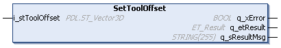
IF_CarrierConfiguration - SetToolOffset (Method)
Description
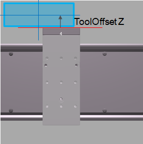
With the method SetToolOffset, you can specify the offset vector from the center point of the carrier to the center point of the tool.
|
Top view |
Side view |
|---|---|
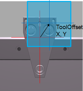
|
|
|
|
For more information on the coordinate system of the carrier, refer to Carrier Coordinate System.
The tool offset is used for calculating the rear offset and the front offset of the carrier based on the ToolDimensions and the ToolOffset as well as the ProductDimensions and the ProductOffset.
For more details on the properties lrRearOffset and lrFrontOffset, refer to the interface IF_CarrierFeedbackConfiguration.
Inputs
|
Input |
Data type |
Description |
|---|---|---|
|
i_stToolOffset |
Specifies the center point of the tool in relation to the center point of the carrier. |
Outputs
|
Output |
Data type |
Description |
|---|---|---|
|
q_xError |
BOOL |
Indicates TRUE if an error has been detected. For details, refer to q_etResult and q_sResultMsg. |
|
q_etResult |
Provides diagnostic and status information as a numeric value. |
|
|
q_sResultMsg |
STRING [255] |
Provides additional diagnostic and status information as a text message. |