Estimate the Orientation of a Target Coordinate System
Overview
This chapter contains examples of how to use FB_TeachingOrientation to estimate the orientation of a target coordinate system with reference to the coordinate system of the robot.
Fixed Coordinate System
If the target coordinate system is not moving, a grid with known positions can be used as a reference for estimating the orientation.
-
The grid must have a minimum of six points; each set must contain a minimum of two points.
-
It is important that the X direction of the grid is aligned to the direction of the X axis of the orientation to teach.
-
If the reference grid is printed on a sheet of paper, the alignment of the grid to the X and Y axes of the target system to teach influences the result of the estimation.
Procedure for Using the Provided Teaching Grid
|
Step |
Action |
|---|---|
|
1 |
Start by printing the provided teaching grid. In this example the Reference Grid. |
|
2 |
Place the printed teaching grid on the physical coordinate system to teach, ensuring that the X and Y axes drawn on the grid are aligned as much as possible with the equivalent axes of the system to teach. Any misalignment between the teaching grid orientation and the coordinate system to teach influences the estimated orientation.
NOTE: Ensure that the teaching grid cannot move with respect to the surface of the system on which it is placed.
|
|
3 |
Define an instance of the teaching function block: |
|
4 |
Call the method SetNumberOfSamplesPerSet to set the number of samples that are stored for each set. In this case the teaching grid is composed of three sets, each one containing two samples. The called method provides a value of 2 as input: |
|
5 (Optional) |
The teaching requires touching points with the robot on the surface of the other system to teach. This procedure is performed with a tool mounted on the robot. The cartesian pose transformation introduced by a tool can be described with ROB.IF_RobotConfiguration.ConfigureTool. Then the tool can be selected with the method ROB.IF_RobotMotion.SetTool. Once a tool is set, the feedback ROB.IF_RobotFeedback.rstRefPositionTCP accounts for that. If a rotation of the tool could influence the TCP position, the orientation must be considered, and it is then required to configure the robot so that the orientation is properly handled (see ROB.IF_RobotConfiguration.MapComponentToDrive). |
|
6 |
Move the robot to a position where it is aligned to the circle marked with the number 1 inside Set 1, as displayed in the graphic. 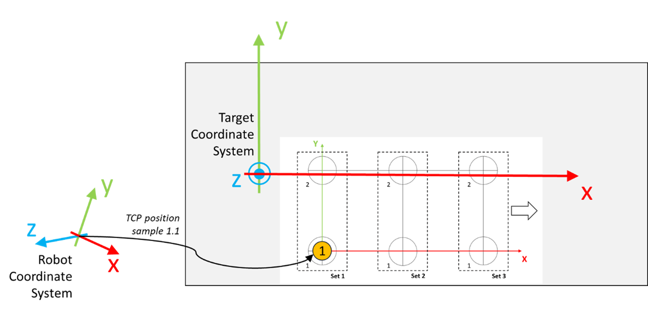
|
|
7 |
Call the method AddSample to store the position of the TCP: Where the variable stCurrentTCPPosition is of type SE_MATH.ST_Vector3D and its value can be obtained for example from the property ROB.IF_RobotFeedback.rstRefPositionTCP.
NOTE: After calling AddSample a first time for the selected set, the value of udiNumberOfSamplesInActiveSet increases by one.
|
|
8 |
Move the robot to a position where it is aligned to the circle marked with the number 2 inside Set 1, as displayed in the graphic. 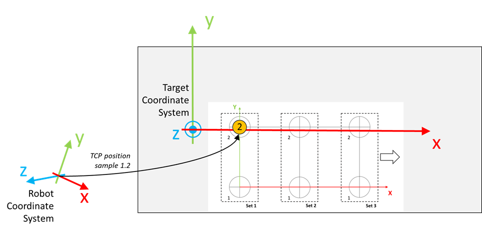
|
|
9 |
Call the method AddSample to store the position of the TCP:
NOTE: After calling AddSample a second time for the selected set, the set is completed and the value of udiNumberOfCompleteSets increases by one.
|
|
10 |
Move the robot to a position where it is aligned to the circle marked with the number 1 inside Set 2, as displayed in the graphic. 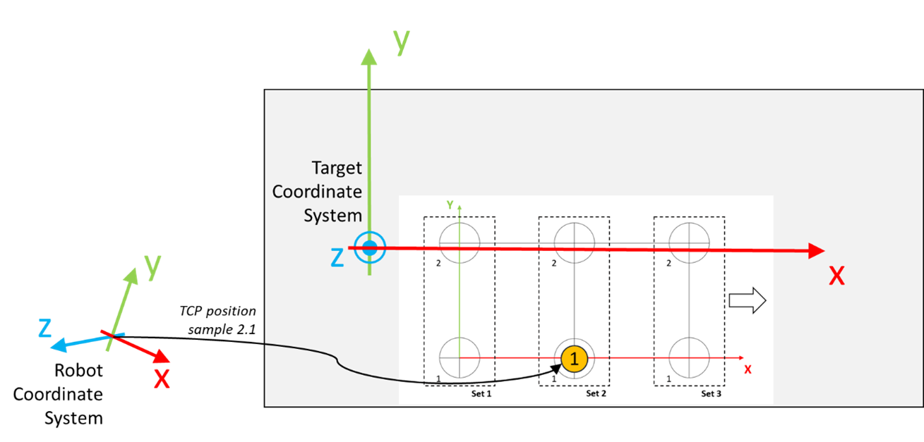
|
|
11 |
Call the method AddSample to store the position of the TCP: |
|
12 |
Move the robot to a position where it is aligned to the circle marked with the number 2 inside Set 2, as displayed in the graphic. 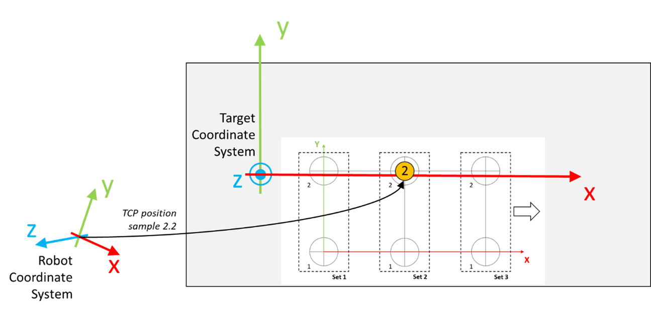
|
|
13 |
Call the method AddSample to store the position of the TCP: |
|
14 |
Move the robot to a position where it is aligned to the circle marked with the number 1 inside Set 3, as displayed in the graphic. 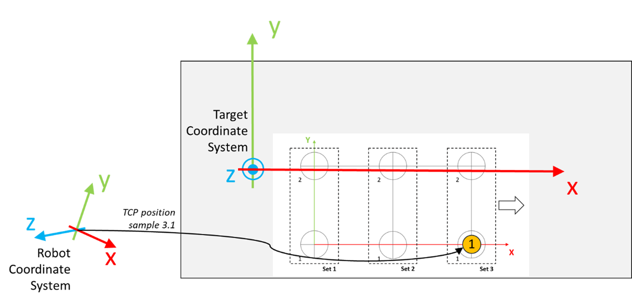
|
|
15 |
Call the method AddSample to store the position of the TCP: |
|
16 |
Move the robot to a position where it is aligned to the circle marked with the number 2 inside Set 3, as displayed in the graphic. 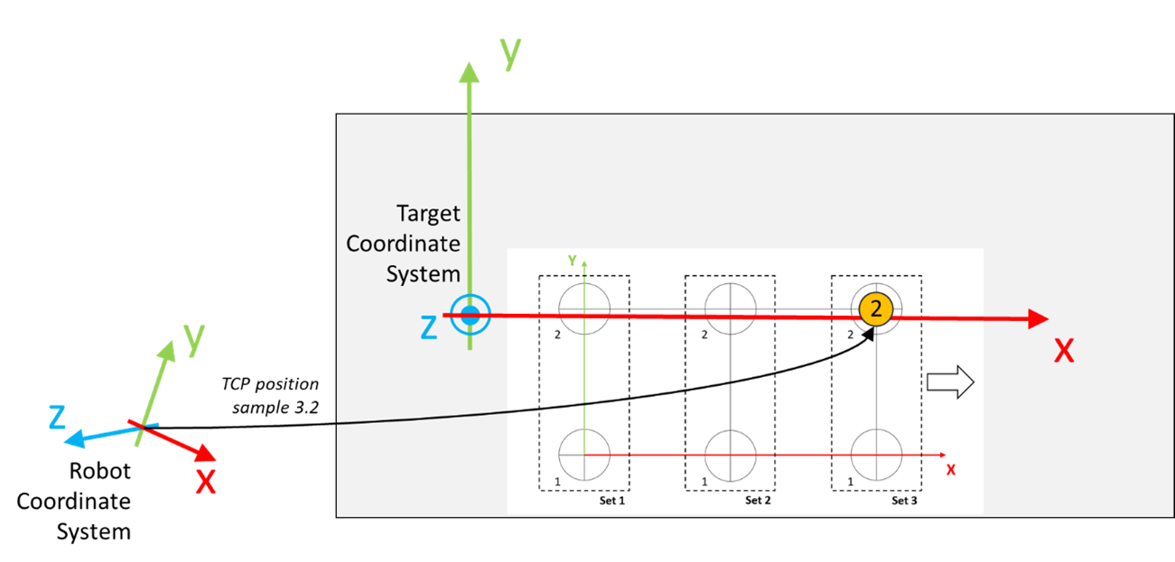
|
|
17 |
Call the method AddSample to store the position of the TCP: |
|
18 |
Call the method EstimateOrientation to estimate the orientation of the target coordinate system based on the acquired sets of samples:
NOTE:
|