Axis Mode
Homing Tab
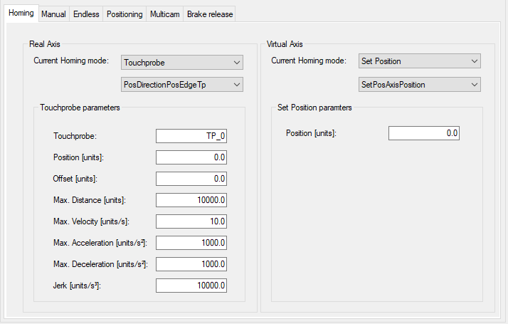
The tab allows you to select and parameterize the homing mode for a (left-hand side) and for a (right-hand side).
Selecting and parameterizing the homing mode for a or for a is done in the same way.
All homing modes of the are supported (refer to the PD_AxisModule Library Guide, AXM.ST_ModuleInterface.ST_Home).
/
|
Element |
Description |
|---|---|
|
|
Select a homing mode (for details see below): Additionally you can select different parameters for the homing mode. For example, for you can select . |
|
|
Enter the parameters for the selected homing mode. For example, . |
Homing modes:
-
Refer to the PD_PacDriveLib Library Guide, PDL.ST_HomeTp and PDL.ET_HomeTpMode.
-
Refer to the PD_PacDriveLib Library Guide, PDL.ST_HomeIn and PDL.ET_HomeInMode.
There are two possibilities to use the sensor value PDL.ST_HomeIn.i_xSensor:
-
You can use the property SR_<AxisName>.xHomingSensor. Refer to the tab.
-
You can write a value to the structure in the Logic method.
The property and the structure variable stSensor.i_xSensor are connected with an OR-condition.
-
-
Refer to the PD_PacDriveLib Library Guide, PDL.ST_HomeLimitSwitch and PDL.ET_HomeLimitSwitchMode.
There are two possibilities to use the sensor value AXM.ST_Main.i_xHwLimitPos/ i_xHwLimitNeg:
-
You can use the property SR_<AxisName>.xHwLimitSwitchPos/ SR_<AxisName>.xHwLimitSwitchNeg. Refer to the tab.
-
You can write a value to the structure in the Logic method.
The property and the structure variable stMain.i_xHwLimitPos/stMain.i_xHwLimitNeg are connected with an OR-condition.
-
-
Refer to the PD_PacDriveLib Library Guide, PDL.ST_HomeTorque and PDL.ET_HomeTorqueMode.
-
Refer to the PD_PacDriveLib Library Guide, PDL.ST_HomeMoveOnPos.
-
Refer to the PD_PacDriveLib Library Guide, PDL.ST_HomeSetPos and PDL.ET_HomeSetPosMode.
-
Refer to the PD_PacDriveLib Library Guide, PDL.ST_HomeSetPos and PDL.ET_HomeSetPosMode.
-
Refer to the PD_PacDriveLib Library Guide, PDL.ST_HomeWritePos.
Manual Tab
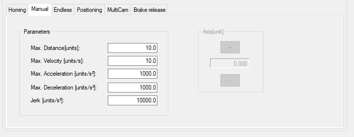
The tab allows you to edit the parameters for the manual mode and helps you to move the axis manually. You can move the axis if the module is online and the manual mode is activated.
For detailed information on the parameters, refer to the PD_AxisModule Library Guide, AXM.ST_Manual).
| WARNING | |
|---|---|
|
Element |
Description |
|---|---|
|
|
Edit the parameters for the manual mode: For detailed information on the parameters, refer to the PD_AxisModule Library Guide, AXM.ST_Manual). |
|
|
Click the buttons (/) to move (jog) along the axis by controlling the corresponding drives. |
Endless Tab
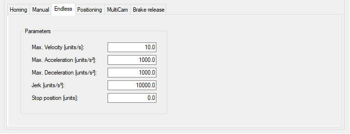
The tab allows you to edit the parameters for the endless mode.
For detailed information on the parameters, refer to the PD_AxisModule Library Guide, AXM.ST_EndlessFeed).
|
Element |
Description |
|---|---|
|
|
Edit the parameters for the endless mode: For detailed information on the parameters, refer to the PD_AxisModule Library Guide, AXM.ST_EndlessFeed). |
Positioning Tab
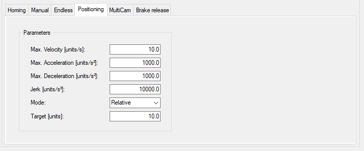
The tab allows you to edit the parameters for the positioning mode.
For detailed information on the parameters, refer to the PD_AxisModule Library Guide, AXM.ST_Positioning).
|
Element |
Description |
|---|---|
|
|
Edit the parameters for the positioning mode: For detailed information on the parameters, refer to the PD_AxisModule Library Guide, AXM.ST_Positioning). |
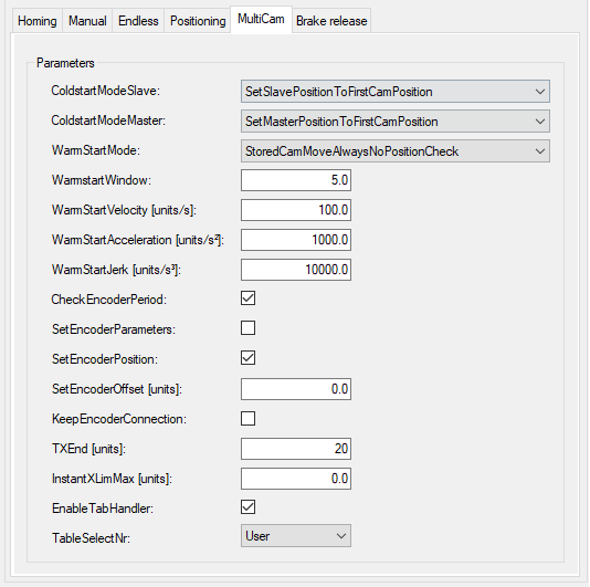
MultiCam
The tab allows you to edit the parameters for the MultiCam mode.
For detailed information on the parameters, refer to the PD_AxisModule Library Guide, AXM.ST_MultiCam).
The tab provides two sections:
|
Element |
Description |
|---|---|
|
|
Edit the parameters for the positioning mode: For detailed information on the parameters, refer to the PD_AxisModule Library Guide, AXM.ST_MultiCam). |
|
Element |
Description |
|---|---|
|
|
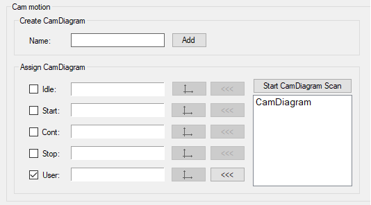
Enter a and click the button. Result: A is displayed in the tree beneath the node. For detailed information on the configuration of a , refer to the PD_PacDriveLib Library Guide, FB_MultiCam description, and to EcoStruxure Machine Expert Programming Guide, Cam Motion Editor. |
|
|
Assign a to a motion sequence.
One can be assigned to multiple motion sequences. |
The description of the motion sequence is stored in a structure of type PDL.ST_MultiCam. It provides the number of motion points (maximum 32), and an array of points of type PDL.ST_CamPoint. By modifying the structure, it is possible to assign various motion sequences to event-driven cycles (for example, idle cycle, start cycle, continuous cycle, stop cycle, user-specific cycle). Up to five can be assign to these five motion sequences. In correspondence with the PD_AxisModule.ET_ParId enumeration type, it can be used to select one of the MultiCam tables. The names in the enumeration represent five cam profiles: , , , , .
As only the PDL.ST_MultiCam structure type is supported by the Smart Template Axis Module, activate the option and select PDL.ST_MultiCam.
At runtime, the system generates the corresponding iq_astMotionPar structure from the assigned .
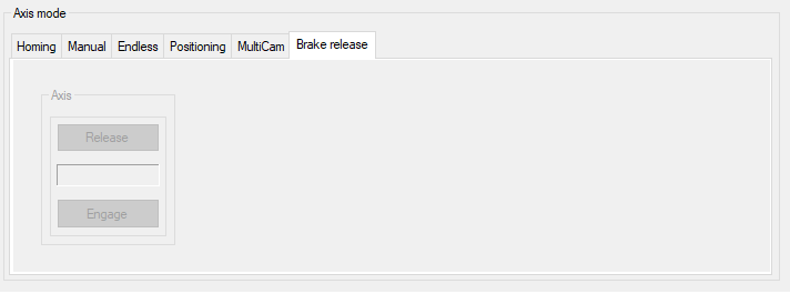
Brake Release Tab
The tab helps you to release/engage the brake of an axis.
You can control the brake if the module is online and the brake release mode is activated.
It is not verified whether the motor is equipped with a brake or not.
|
Element |
Description |
|---|---|
|
|
The indicator between the and the button displays the state of the brake.
NOTE: The buttons are only enabled if the axis module is in operation mode BrakeRelease.
|