Multicarrier Configuration
Multicarrier Configuration Editor
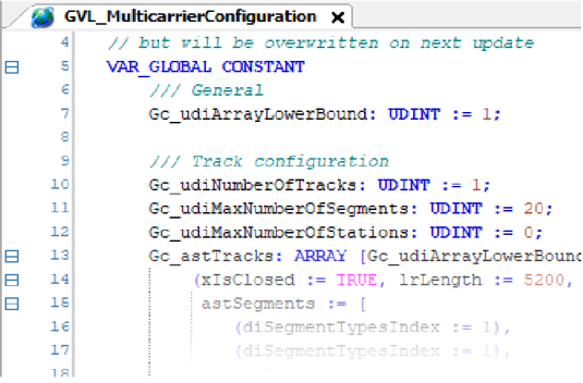
The project uses the generated variables from the global variable list GVL_MulticarrierConfiguration of the editor. The global variable list GVL_MulticarrierConfiguration can be found in the folder .
-
You change the configuration in the global variable list GVL_MulticarrierConfiguration (see example below).
-
You change the object and update the code.
SR_MainMachine
In the action SR_MainMachine.Start_Action, you find an additional state machine for parametrizing and activating the Multicarrier. In the project, the Sercos phase is set to zero per default.
The following graphic illustrates the different states along with comments for the corresponding processes:
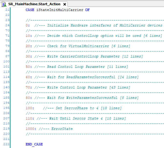
In the following, you find some detailed descriptions for state 0, state 10, state 30 as well as state 60 and 70:
|
Stage |
Description |
|---|---|
|
1 |
The device objects must be assigned to an interface in the local structure stMulticarrierModule. Use the methods AssignSegments and AssignCarriers.
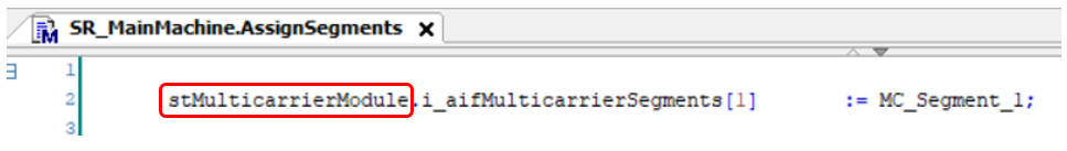 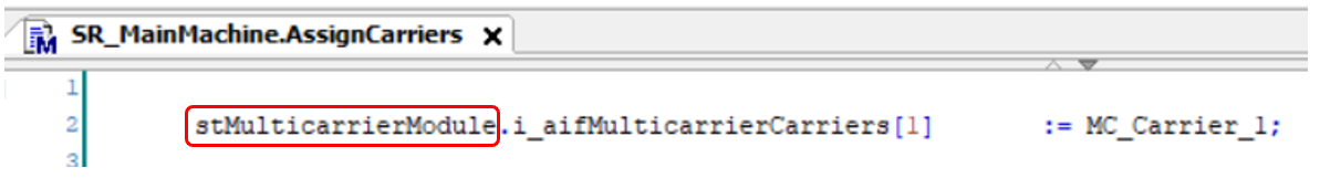
The structure is transferred to the SR_MulticarrierModule.
NOTE: The project is conceived for 30 segments and 70 carriers. If you want to increase these numbers, you must add the appropriate number of segments/carriers in the methods AssignSegments and AssignCarriers.
|
|
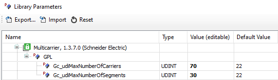
2 |
There are two global parameters in the Multicarrier library to set the corresponding number of hardware elements. These variables must also be adjusted if you change the number of carriers or segments:
|
|
3 |
In case of running a physical device, the working mode is set to for the appropriate segments by setting the variable Gc_xVirtualMulticarrier to FALSE. In case of running a virtual device, the working mode is set to for the appropriate segments by setting the variable Gc_xVirtualMulticarrier to TRUE. 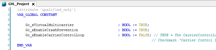
|
|
4 |
The working direction from the global variable list GVL_MulticarrierConfiguration is written to the track object.

|
|
5 |
The Sercos phase is set to 2. |
State 10
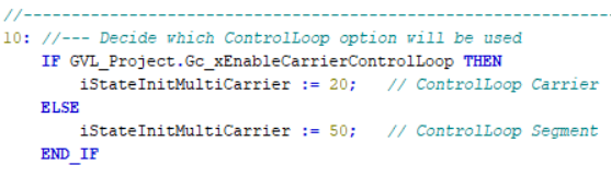
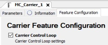
It is the status of the global variable Gc_xEnableCarrierControlLoop that determines whether the control loop parameters of the carrier or of the segment (default setting) are used.
State 30
Write the control loop parameters per carrier.
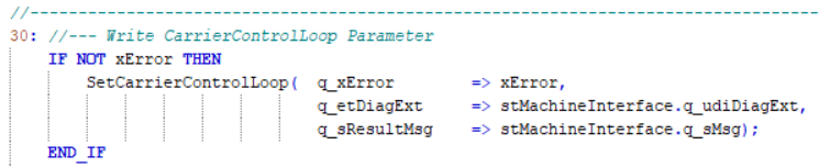
For more information on configuring the control loop settings per carrier, refer to Lexium™ MC multi carrier Device Objects and Parameters Guide.
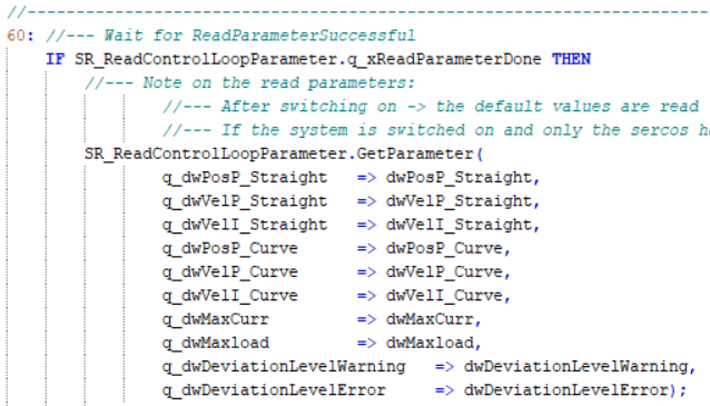
State 60
Read the default control loop parameters from the segments.
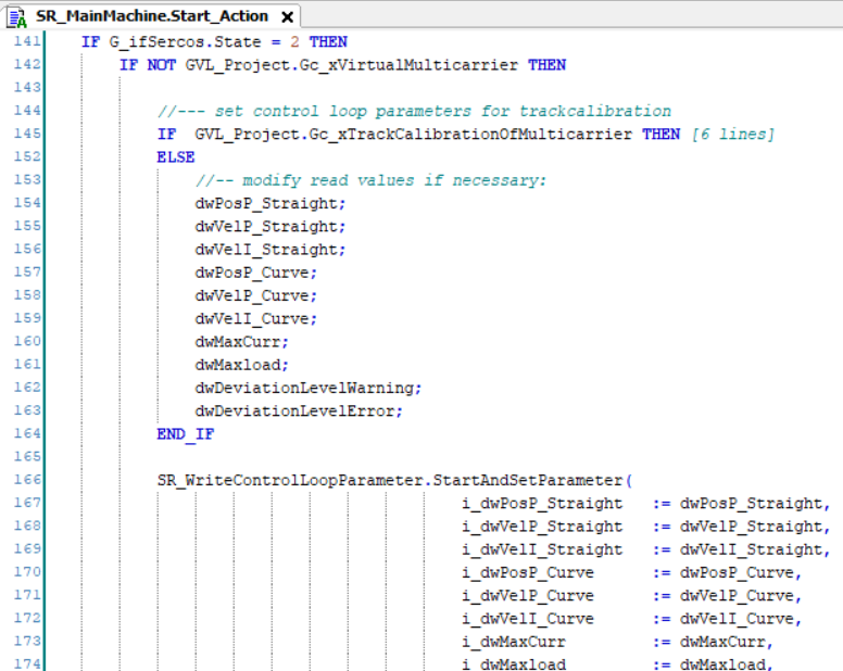
State 70
Modify the default control loop parameters and write them to the segments.
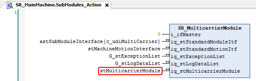
SR_MulticarrierModule
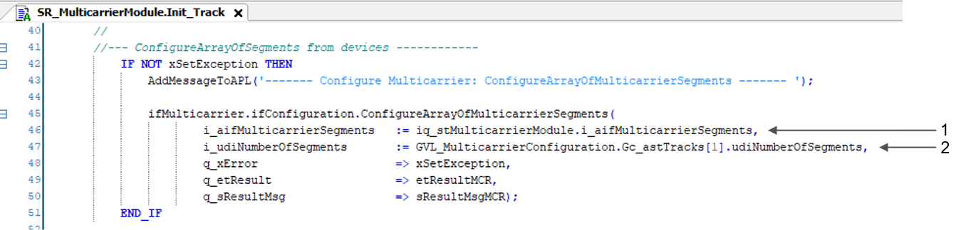
For mapping the hardware configuration to the Multicarrier library, the action Init_Track in the subroutine SR_MulticarrierModule is used.
|
Item |
Description |
|---|---|
|
1 |
Structure with segment interfaces transferred from SR_MainMachine |
|
2 |
Variable from the editor |