DIN Rail Installation
Grounding Function
The DIN rail must be attached to a conductive backplane that itself is connected to a protective ground (PE).
In the mounting channel of each piece of the TM5 equipment is a metal spring contact. When properly mounted on a metal DIN rail, these contacts provide connection to the functional ground (FE) for the entire TM5 System.
Mounting the DIN Rail
The TM5 System components are designed for mounting on rail conforming to IEC 60715.
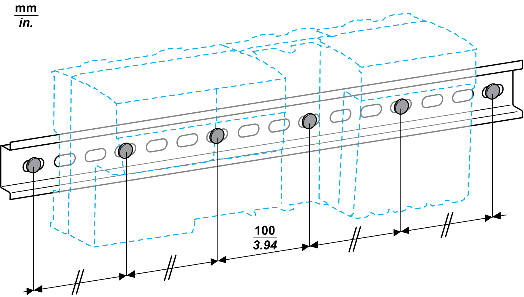
To help achieve the stated TM5 System performance characteristics, the mounting hardware must be installed at the end positions and at 100 mm (3.94 in.) maximum increments along the length of the rail.
| WARNING | |
|---|---|
The following figure illustrates the mounting requirements for the DIN rail:
Low profile NSYSDR200D DIN rail may be used with low profile mounting hardware such as flat head screws with countersunk mounting holes.