Color Coding of the TM5 Safety-Related System
Overview
The following figure shows colors of the TM5 Safety-Related System components:
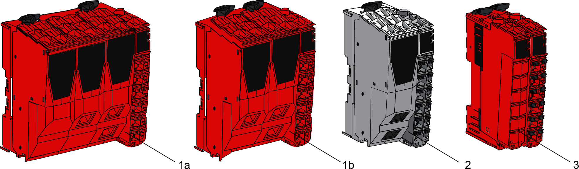
1a Safety Logic Controller TM5CSLC100FS/TM5CSLC200FS
1b Safety Logic Controller TM5CSLC300FS/TM5CSLC400FS
2 Non-safety-related Sercos III Bus Interface TM5NS31
3 TM5 Safety-Related System I/O Module
Safety Logic Controller Color Assignment
The Safety Logic Controller and its removable terminal block are colored in red.
Memory Key Color Assignment
The Memory Key of the Safety Logic Controller is gray and red.
For more information refer to Memory Key.
Sercos III Bus Interface Color Assignment
Two colors are used for the four components of a Sercos III Bus Interface:
-
White for the:
-
Sercos III Bus Interface bus base and,
-
Sercos III Bus Interface module.
-
-
Gray for the:
-
Interface Power Distribution Module (IPDM) and,
-
associated terminal block.
-
Slice Color Assignment
The components of a TM5 Safety-Related System module are colored in red.
| DANGER | |
|---|---|