The digital signal processor module TM5SE1MISC20005 is used for encoder emulation, frequency inverters, or servo axes with the speed follow function can follow a real or virtual master axis.
The TM5SE1MISC20005 module provides the following features:
o3 digital 5 V channels, configurable as inputs or outputs
o2 digital 24 V input channels
oEncoder evaluation (A/B) with one reference pulse
The following table describes the main characteristics of the digital signal processor module TM5SE1MISC20005:
|
Main characteristics |
|
|---|---|
|
Number of digital inputs |
2 |
|
Number of input channels |
1 |
|
Encoder type |
Incremental |
|
Output counting frequency |
maximum 4 MHz using 4 x evaluation |
|
Encoder supply |
24 Vdc |
|
Encoder output |
5 V symmetrical |
|
Counter functions |
Encoder emulation (A/B) with one reference pulse |
|
Resolution |
16/32-bit |
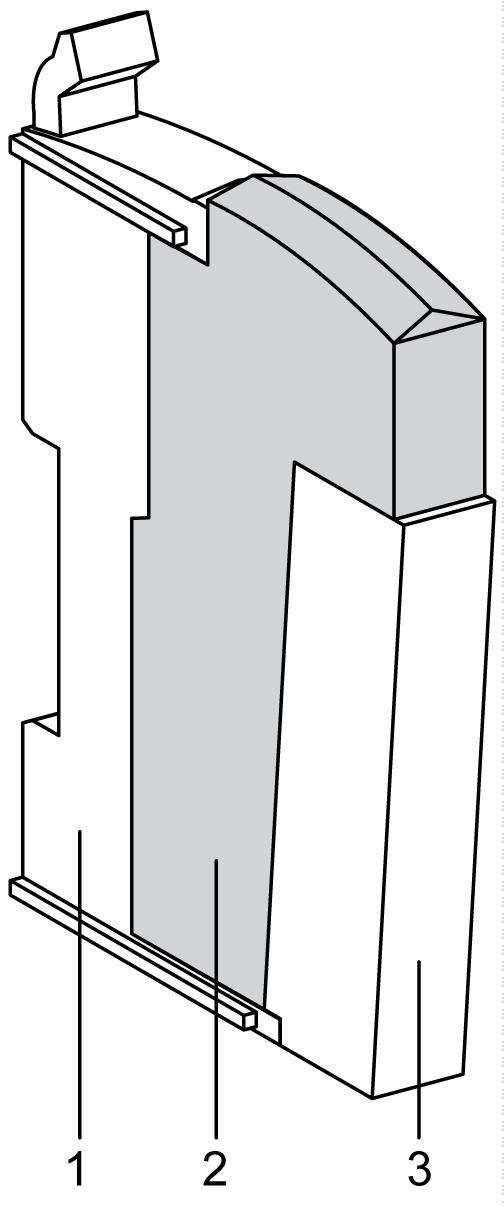
The illustration below shows the TM5SE1MISC20005:

The following table shows the references for the terminal block and the bus bases associated with the TM5SE1MISC20005:
|
Number |
Reference |
Description |
Color |
|---|---|---|---|
|
1 |
TM5ACBM11 or TM5ACBM15 |
Bus base
Bus base with address setting |
White
White |
|
2 |
TM5SE1MISC20005 |
Electronic module |
White |
|
3 |
TM5ACTB12 |
Terminal block, 12 pins |
White |
NOTE: For more information, refer to TM5 bus bases and terminal blocks.
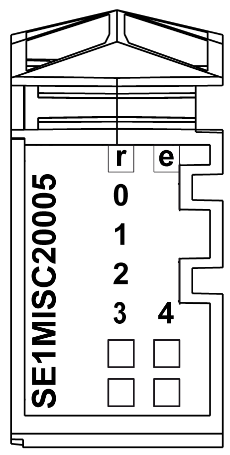
The following illustration describes the LEDs for TM5SE1MISC20005:

The table shows the TM5SE1MISC20005 status LEDs:
|
LED |
Color |
Status |
Description |
|---|---|---|---|
|
r |
Green |
Off |
No power supply |
|
Single flash |
Reset state |
||
|
Double flash |
Boot state (during firmware update) Depending on the configuration, a firmware update can take up to several minutes. |
||
|
Flashing |
Preoperational state |
||
|
On |
Normal operation |
||
|
e
|
Red
|
Off |
OK or no power supply |
|
On |
Error detected or reset state |
||
|
Single flash |
Input / output error detected. |
||
|
Double flash |
System error detected. |
||
|
Triple flash |
I/O error and system error occur together. |
||
|
0-4 |
Green |
On |
Status of the corresponding digital signal. |