The table below provides the main characteristics of the TM7BAM4VLA block:
|
Main characteristics |
||
|---|---|---|
|
Number of input channels |
2 |
|
|
Number of output channels |
2 |
|
|
Signal type |
Voltage |
|
|
Input range |
-10...+10 Vdc |
|
|
Output range |
-10...+10 Vdc |
|
|
Resolution |
11 bits + sign |
|
|
Sensor and actuator connection type |
M12, A coded, female connector type |
|
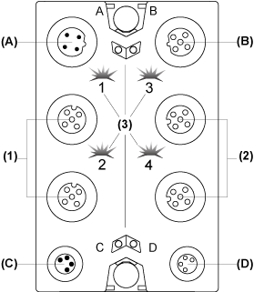
The following figure shows the TM7BAM4VLA block:

(A) TM7 bus IN connector
(B) TM7 bus OUT connector
(C) 24 Vdc power IN connector
(D) 24 Vdc power OUT connector
(1) Input connectors
(2) Output connectors
(3) Status LEDs
Connector and Channel Assignments
The table below provides the connector and channel assignments of the TM7BAM4VLA block. For further information, refer to I/O Configuration Tab:
|
I/O connectors |
I/O status LEDs |
Channel type |
Channels |
|---|---|---|---|
|
1 |
1 |
Input |
I0 |
|
2 |
2 |
Input |
I1 |
|
3 |
3 |
Output |
Q0 |
|
4 |
4 |
Output |
Q1 |
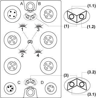
The following figure shows the status LEDs of the TM7BAM4VLA block:

(1) TM7 bus status LEDs, set of two LEDs: 1.1 (green) and 1.2 (red)
(2) I/O status LEDs, composed of two sets of two LEDs: 1 and 2 (green), 3 and 4 (yellow)
(3) I/O block status LEDs, set of two LEDs: 3.1 (green) and 3.2 (red)
The table below provides the TM7 bus status LEDs of the TM7BAM4VLA block:
|
TM7 bus status LEDs |
Description |
|
|---|---|---|
|
LEDs 1.1 |
LEDs 1.2 |
|
|
OFF |
OFF |
No power supply on TM7 bus |
|
ON |
ON |
TM7 bus in preoperational state: opower supply on TM7 bus and oblock not initialized |
|
ON |
OFF |
TM7 bus in operational state |
|
OFF |
ON |
TM7 bus error detected |
The table below provides the I/O status LEDs of the TM7BAM4VLA block:
|
Channel LEDs |
State |
Description |
|---|---|---|
|
1 and 2 |
OFF |
Open connection or sensor/actuator is disconnected |
|
Flashing |
Overflow or underflow of the input signal |
|
|
ON |
The analog/digital converter is running, a value is available |
|
|
3 and 4 |
OFF |
The enable relay is not closed yet, there is not any value available other than 0 |
|
ON |
The analog/digital converter is running, a value is available |
The table below provides the I/O block status LEDs of the TM7BAM4VLA block:
|
Block status LEDs |
State |
Description |
|---|---|---|
|
3.1 |
OFF |
No power supply |
|
Single Flash |
Reset state |
|
|
Flashing |
Preoperational state |
|
|
ON |
Operational state |
|
|
3.2 |
OFF |
OK or no power supply |
|
Single Flash |
Detected error for an I/O channel. Overflow or underflow of the input signal |
|
|
Double Flash |
Power supply not in the valid range |
|
|
ON |
Detected error or reset state |