To configure the TM5 Manager, proceed as follows:
|
Step |
Action |
|---|---|
|
1 |
In the Devices tree, expand the TM5 node. |
|
2 |
Double-click the TM5_Manager node. Result: The TM5 Manager configuration window is displayed. |
|
3 |
Select the I/O Configuration tab. |
Parameters of the I/O Configuration:
|
Parameter |
Value |
Default Value |
Unit |
Description |
|---|---|---|---|---|
|
Bus Cycle Time |
0.5 ms 1 ms 2 ms 3 ms 4 ms 5 ms |
1 ms |
ms |
Expansion Bus Cycle Time |
|
Maximum number of physical slots |
Number of Embedded modules...250 |
250 |
- |
Maximum number of modules on the expansion bus. |
|
Name of FW repository |
Not configurable |
- |
- |
This parameter indicates the Flash memory repository for the modules firmware. |
|
Maximum bus length in meters (feet) |
1...2500 (3.28...8202) |
100 (328) |
m |
Total cable length used on the expansion bus. |
NOTE: For more information about the maximum capacities of your system, refer to the TM5 / TM7 System Planning and Installation Guide.
Bus Cycle Time can be configured from 0.5 to 5 ms. Very fast cycles reduce the idle time for handling monitoring, diagnostics and acyclic commands.
The Bus Cycle Time follows 2 rules:
oBe longer than the greatest Minimum Cycle Time of any expansion module or block in the configuration.
oBe long enough to permit the data exchange with all the modules and the blocks.
The Minimum Cycle Time of a module or of a block is the time needed by the module or the block to perform I/O management. If the Bus Cycle Time is shorter than this minimum value, the module will not operate properly.
The Minimum I/O Update Time of a module or block is the time needed by the module or block to update I/O on the bus. If the Bus Cycle Time is shorter than this minimum value, the I/O will be updated on the bus at the next Bus Cycle Time.
At the beginning of each task, the %I memory variable for the inputs used in the task is updated with the physical state of the input.
At the end of each task, the used %Q memory variable value for the outputs is updated.
On the next bus cycle after the end of the task configured as the Bus cycle task, the physical output is updated from the %Q memory variable value.
For more details on Bus cycle task, refer to the controller PLC settings tab.
To display the estimated power consumption of the expansion modules:
|
Step |
Action |
|---|---|
|
1 |
Right-click the TM5_Manager node of the Device tree. |
|
2 |
Select Power consumption. |
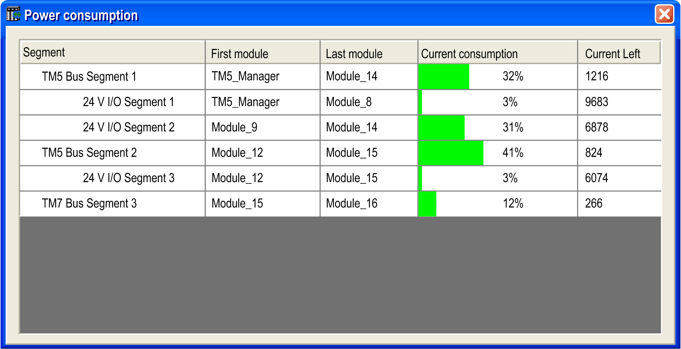
NOTE: The current consumption figures presented by the Power consumption function are based on assumed values, and not on actual current measurements. The assumed values for the outputs are based on classic loads but can be adjusted using the 24 Vdc I/O segment external current setting in the I/O Configuration tab of each module (refer to the Modicon TM5 Expansion Modules Configuration Programming Guide). The assumptions for input signals are based on known internal loads and are therefore not modifiable. While the use of the Power consumption function to test the power budget is required, it is no substitute for actual and complete system testing and commissioning. Refer to the TM5 TM7 System Planning and Installation Guide.