CANmotion Interface Configuration
On the CAN1 connector, you can connect a CANmotion manager:
oIt accepts only the following motion devices (with a specific interface for CANmotion bus):
oLexium 05 Servo drive
oLexium 23 Servo drive
oLexium 32 Servo drive
oLexium SD3 Stepper drive
oGeneric CAN devices cannot be added.
To configure the communication port of your controller, proceed as follows:
|
Step |
Action |
|---|---|
|
1 |
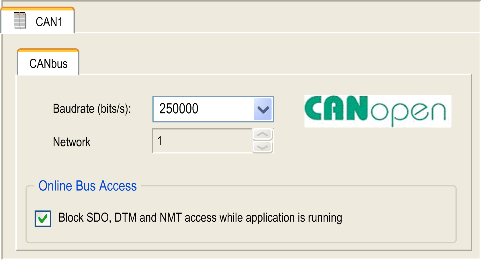
In the Devices tree, double-click CAN1. Result: The configuration dialog box for CAN communications will be displayed. |
|
2 |
Configure the baud rate (by default: 250.000 bit/s): 
NOTE: On CANmotion, only the following baud rates are supported: 250, 500 and 1000 kBaud |
To add the CANmotion Manager, proceed as follows:
|
Step |
Action |
|---|---|
|
1 |
Select the CANmotion in the Hardware Catalog, drag it to the Devices tree, and drop it on one of the highlighted nodes. For more information on adding a device to your project, refer to: • Using the Drag-and-drop Method • Using the Contextual Menu or Plus Button |
|
2 |
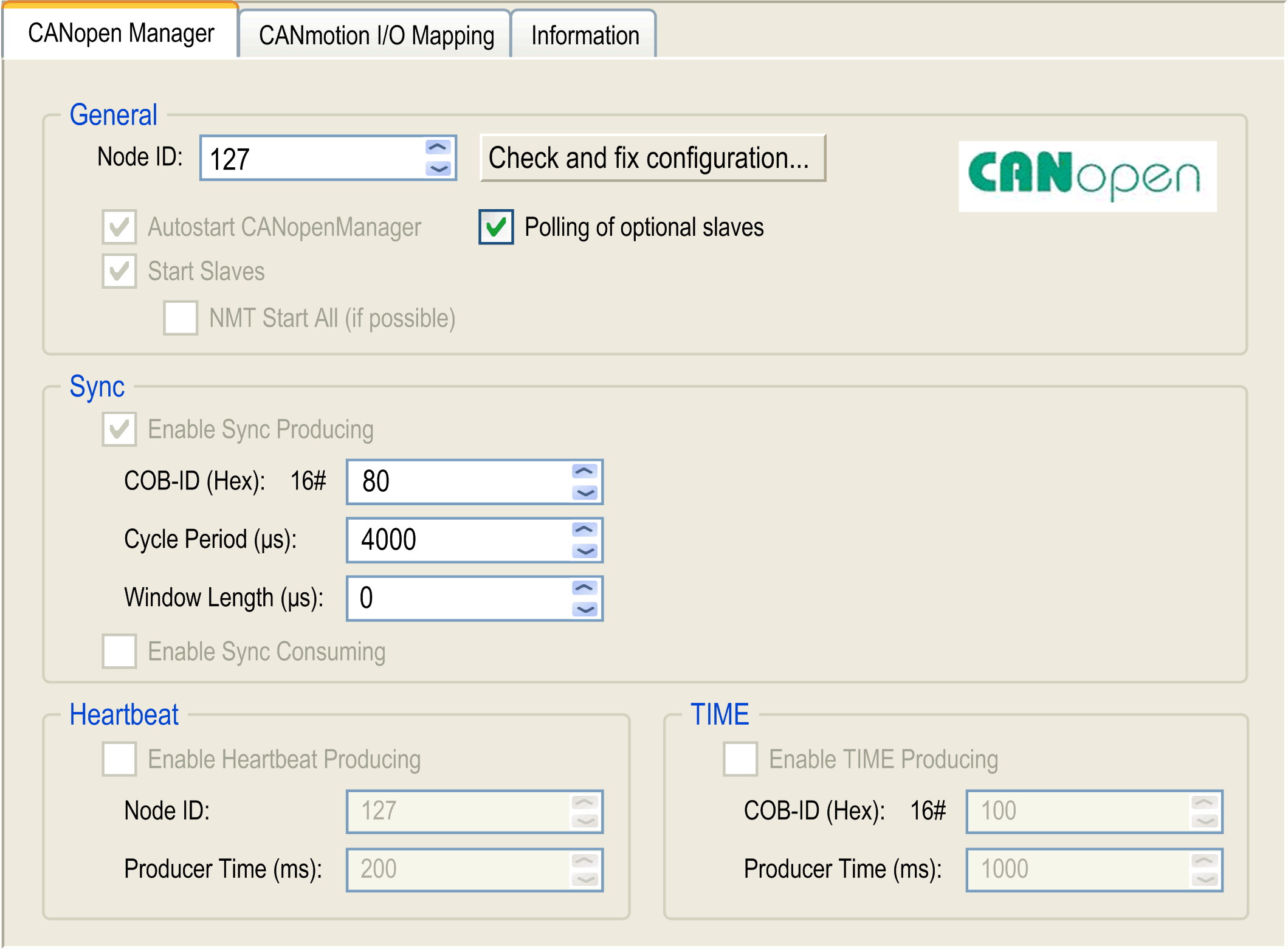
Double-click the CANmotion Manager you added. Result: The CANmotion Manager configuration window appears: 
|
CANmotion Cycle Time Configuration
The CANmotion cycle time is configured with parameter Cycle period (µs). Configure it from 1 to 20 ms in 1 ms steps.
Configure the Cycle period (µs) value to allow sufficient time for both of the following to be true:
oThe program processing defined in your Motion task must have enough time to execute in full. Test the execution time of your Motion task under all operating conditions to determine this value.
oThe Cycle period (µs) must be of sufficient length to allow the physical exchange of all PDO and SDO data between the controller and all of the configured devices.
NOTE: If you do not configure a sufficient Cycle period (µs), this can result in a task or system watchdog exception or even a detected synchronization error for the controlled devices.
Calculating the Minimum Physical Data Exchange Period
This minimum time necessary to physically exchange PDO and SDO objects depends on:
oThe baud rate (transmission speed)
oThe number of axes declared
oThe number of CANmotion services used (the TPDO and RPDO associated with the chosen cyclic synchronous mode, and the asynchronous messaging SDO and optional TPDO if selected).
For example: Using an axis in CSV or in CST mode will require more time as 1 extra RDO and 1 extra TPDO are exchanged compared to the CSP mode.
The table below explains how to calculate the CANmotion theoretical minimum time for the physical exchange of PDO and SDO data:.
|
Baud rate |
250 Kbit/s |
500 Kbit/s |
1 Mbit/s |
|
|---|---|---|---|---|
|
CANmotion service |
Basis |
Time consumption (ms) |
||
|
Default traffic (Synchronous bit + reserved SDO exchange + others) |
per CANmotion |
1.01 |
0.66 |
0.48 |
|
Drive in CSP mode only |
per drive |
0.92 |
0.46 |
0.23 |
|
Drive in CST or CSV mode |
per drive |
1.89 |
0.95 |
0.47 |
|
Optional TPDO |
header (per TPDO per drive) |
0.19 |
0.10 |
0.05 |
|
per byte per TPDO |
0.04 |
0.02 |
0.01 |
|
Example of calculation:
|
Description |
Value |
|---|---|
|
CANmotion with a baud rate of 1 Mbit/s |
0.48 |
|
Drive 1 and drive 2 are in CSP. Drive 3 in CST |
2x0.23 + 0.47 |
|
1 optional TPDO is configured to read torque value (2 bytes) of drive 1 |
0.05 + 2x0.01 |
|
1 optional TPDO is configured to read torque value (4 bytes) of drive 3 |
0.05 + 4x0.01 |
|
Minimum time required to physically exchange data between the controller and motion devices |
1.57 ms. |
In the example above, the minimum time required for the physical data exchange is 1.57 ms. This value must be compared to the tested duration of the Motion Task processing. Define a Cycle period at least 20% longer than the larger of the two values to accommodate variations in the duration of the Motion Task and of data exchanges.
NOTE: The performance values provided are calculated based upon the assumption that you have complied with all installation instructions for the equipment. The actual performances can vary depending on such factors as electromagnetic interference, wiring quality and conformance to CAN wiring guides, and a daisy chain topology.
To add a CANmotion slave device, proceed as follows:
|
Step |
Action |
|---|---|
|
1 |
Select the Devices & Modules tab in the Hardware Catalog. |
|
2 |
Select Communication > CANopen and choose the CANmotion slave device to add, drag-and-drop it onto the CANx node of the Devices tree. |
CANmotion Lexium 32 Device Configuration
To add and configure the CANmotion Lexium32 Device, proceed as follows:
|
Step |
Action |
|---|---|
|
1 |
Select the Devices & Modules tab in the Hardware Catalog and click Motor Control. |
|
2 |
Select Servos > Lexium 32 A in the list, drag-and-drop the item onto the CANmotion node of the Devices tree. |
|
3 |
In the Devices tree, double-click Lexium 32 A. Result: The Lexium_32_A configuration window appears. |
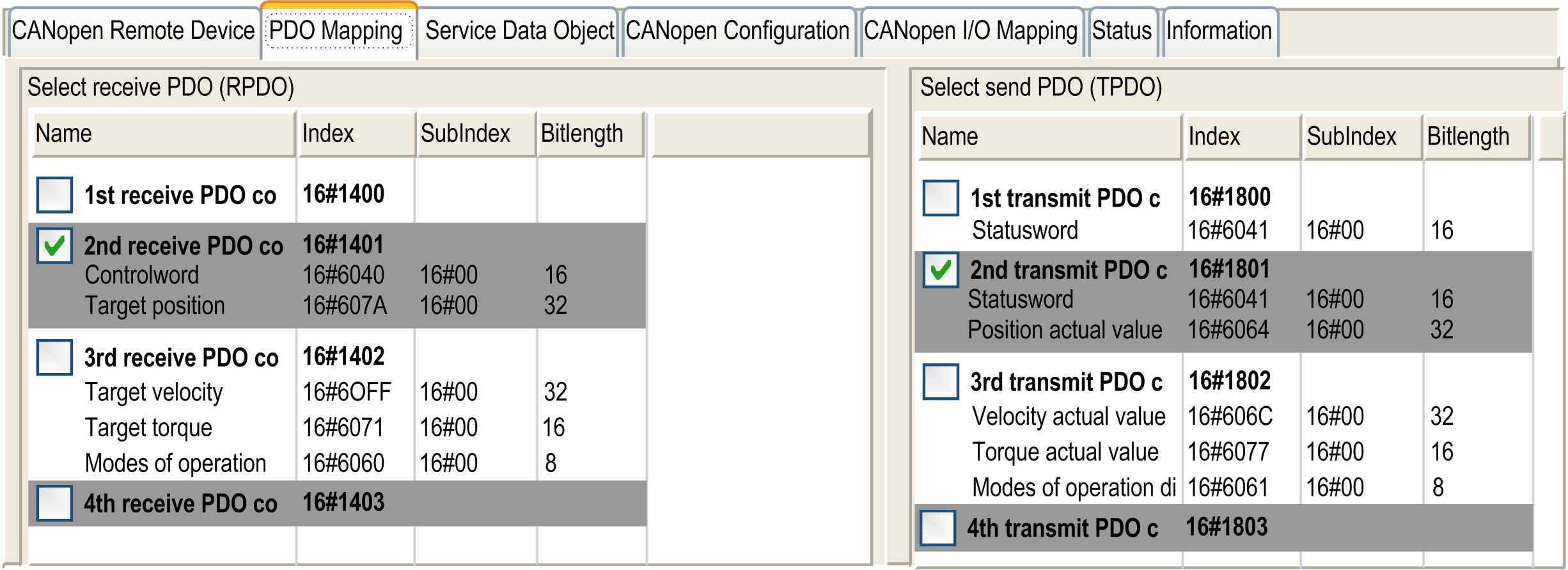
PDO mapping screen:

The default PDO mapping configuration of CANmotion slave is suitable for most implementations of the Cyclic Synchronous Position (CSP). If cyclic synchronous torque mode, cyclic synchronous velocity mode or optional TPDO are needed the PDO mapping has to be modified as follows:
|
|
Default status |
Function |
|---|---|---|
|
1st Receive PDO |
Not activated by default |
Not used. Do not activate these options. |
|
1st Transmit PDO |
||
|
2nd Receive PDO |
Activated by default |
Used for all modes (CSP, CSV & CST) Cannot be deactivated Mapping cannot be modified |
|
2nd Transmit PDO |
||
|
3rd Receive PDO |
Not activated by default |
Used for CST and CSV only Should be activated only if CST or CSV are needed Mapping cannot be modified |
|
4th Transmit PDO |
Not activated by default |
Optional TPDO should be activated only if an optional TPDO is needed Mapping can be modified in the window Send PDO Mapping only accessible if Enable Expert PDO Settings is enabled: For more information, refer to EcoStruxure Machine Expert online help, chapter Programming with EcoStruxure Machine Expert / Device Editors / CANbus Configuration Editor / CANopen Device. |
NOTE: The first Receive PDO and first Transmit PDO mapping options are deactivated by default. If activated, they can cause saturation of the CANmotion bus traffic and delay or prevent motion commands to devices on the bus.
|
|
|
UNINTENDED EQUIPMENT OPERATION |
|
Do not activate the first Receive PDO or first Transmit PDO options. |
|
Failure to follow these instructions can result in death, serious injury, or equipment damage. |