Connection PTI (CN5, Pulse Train In)
General
P/D (pulse/direction), A/B signals or CW/CCW signals can be connected to the PTI connection (Pulse Train In, CN5).
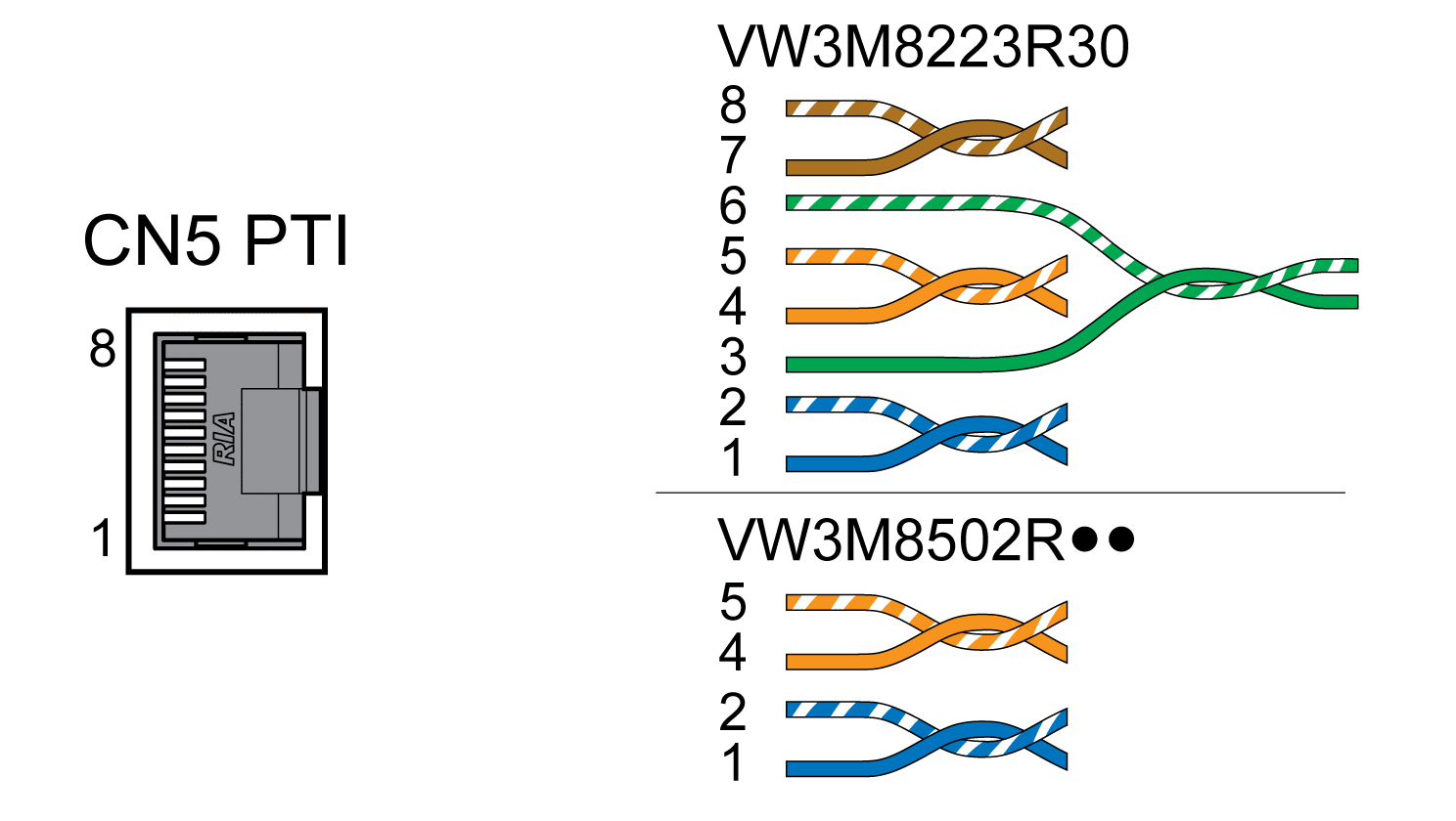
It is possible to connect 5 V signals or 24 V signals, see Input PTI (CN5). Pin assignments and cables are different.
Incorrect or interfered signals as reference values can cause unintended movements.
| WARNING | |
|---|---|
Cable Specifications PTI
|
Shield: |
Required, both ends grounded |
|
Twisted Pair: |
Required |
|
PELV: |
Required |
|
Minimum conductor cross section: |
0.14 mm2 (AWG 24) |
|
Maximum cable length: |
100 m (328 ft) with RS422 10 m (32.8 ft) with push-pull 1 m (3.28 ft) with open collector |
Use pre-assembled cables to reduce the risk of wiring errors, see Accessories and Spare Parts.
Connection Assignment PTI 5 V
Wiring diagram Pulse Train In (PTI) 5 V

P/D signals 5 V
|
Pin |
Signal |
Pair |
Meaning |
|---|---|---|---|
|
1 |
PULSE(5V) |
2 |
Pulse 5V |
|
2 |
PULSE |
2 |
Pulse, inverted |
|
4 |
DIR(5V) |
1 |
Direction 5V |
|
5 |
DIR |
1 |
Direction, inverted |
A/B signals 5 V
|
Pin |
Signal |
Pair |
Meaning |
|---|---|---|---|
|
1 |
ENC_A(5V) |
2 |
Encoder channel A 5V |
|
2 |
ENC_A |
2 |
Encoder channel A, inverted |
|
4 |
ENC_B(5V) |
1 |
Encoder channel B 5V |
|
5 |
ENC_B |
1 |
Encoder channel B, inverted |
CW/CCW signals 5 V
|
Pin |
Signal |
Pair |
Meaning |
|---|---|---|---|
|
1 |
CW(5V) |
2 |
Pulse positive 5V |
|
2 |
CW |
2 |
Pulse positive, inverted |
|
4 |
CCW(5V) |
1 |
Pulse negative 5V |
|
5 |
CCW |
1 |
Pulse negative, inverted |
| WARNING | |
|---|---|
Connecting Pulse Train IN (PTI) 5 V
-
Connect the connector to CN5. Verify correct pin assignment.
-
Verify that the connector locks snap in properly.
Connection Assignment PTI 24 V
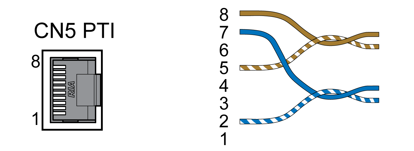
Note that the wire pairs for 24 V signals require assignments different from those for 5 V signals. Use a cable that complies with the cable specification. Assemble the cable as shown in the illustration below.
Wiring diagram Pulse Train In (PTI) 24 V.

P/D signals 24 V
|
Pin |
Signal |
Pair |
Meaning |
|---|---|---|---|
|
7 |
PULSE(24V) |
A |
Pulse 24V |
|
2 |
PULSE |
A |
Pulse, inverted |
|
8 |
DIR(24V) |
B |
Direction 24V |
|
5 |
DIR |
B |
Direction, inverted |
A/B signals 24 V
|
Pin |
Signal |
Pair |
Meaning |
|---|---|---|---|
|
7 |
ENC_A(24V) |
A |
Encoder channel A 24V |
|
2 |
ENC_A |
A |
Encoder channel A, inverted |
|
8 |
ENC_B(24V) |
B |
Encoder channel B 24V |
|
5 |
ENC_B |
B |
Encoder channel B, inverted |
CW/CCW signals 24 V
|
Pin |
Signal |
Pair |
Meaning |
|---|---|---|---|
|
7 |
CW(24V) |
A |
Pulse positive 24V |
|
2 |
CW |
A |
Pulse positive, inverted |
|
8 |
CCW(24V) |
B |
Pulse negative 24V |
|
5 |
CCW |
B |
Pulse negative, inverted |
| WARNING | |
|---|---|
Connecting Pulse Train In (PTI) 24 V
-
Connect the connector to CN5. Verify correct pin assignment.
-
Verify that the connector locks snap in properly.