TM3DQ32UK Wiring Diagram
Introduction
These expansion modules have two built-in HE10 (MIL 20) connectors for the connection of outputs and power supply.
Telefast sub-bases are not compatible with this module.
Wiring Diagram
The following figure illustrates the connections between the outputs, the actuators, and their commons:
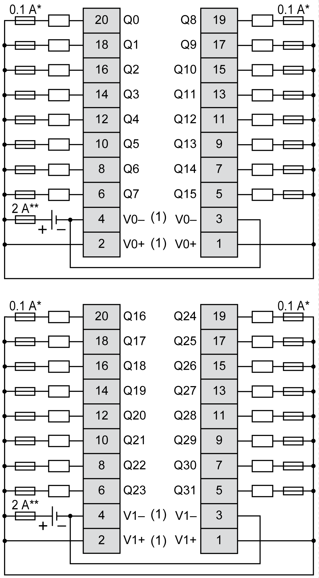
* Type T fuse
** Type F fuse
(1) The V0+ terminals are connected internally.
The V0- terminals are connected internally.
The V1+ terminals are connected internally.
The V1- terminals are connected internally.
The V0+ and V1+ terminals are not connected internally.
The V0- and V1- terminals are not connected internally.
For information about 24 Vdc power supply, refer to DC Power Supply Characteristics.