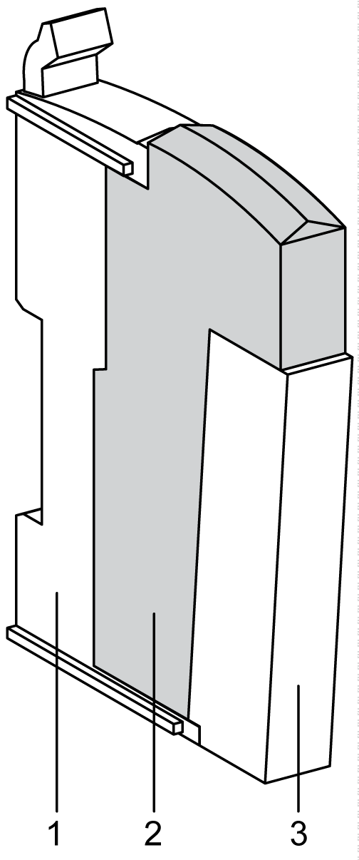
The table below describes the main characteristics of the TM5SBER2 electronic module:
|
Main Characteristics |
|
|---|---|
|
Function |
Receives the TM5 data bus |
|
Maximum bus length |
2500 m (8202.1 ft) |
|
Maximum cable distance between Transmitter and Receiver |
100 m (328.1 ft) |
|
Power distribution |
oTM5 power bus o24 Vdc I/O power segment |
The following figure and table give the references to create a slice with the TM5SBER2 electronic module:

|
NOTICE |
|
ELECTROSTATIC DISCHARGE |
|
oInstall a right bus base locking plate to the rightmost slice of all configurations. oInstall a left bus base locking plate to the first slice of all remote configurations. |
|
Failure to follow these instructions can result in equipment damage. |
|
Number |
Model Number |
Description |
Color |
|---|---|---|---|
|
1 |
TM5ACBM01R or TM5ACBM05R |
Bus base
Bus base with address setting |
Gray
Gray |
|
2 |
TM5SBER2 |
Electronic module |
Gray |
|
3 |
TM5ACTB12PS |
Terminal block, 12-pins |
Gray |
NOTE: For more information, refer to TM5 bus bases and terminal blocks.
The following figure shows the status LEDs for TM5SBER2:

The table below describes the TM5SBER2 status LEDs:
|
LED |
Color |
Status |
Description |
|---|---|---|---|
|
r |
Green |
Off |
No power supply |
|
Single Flash |
Reset state |
||
|
Flashing |
Preoperational state |
||
|
On |
Run state |
||
|
e |
Red |
Off |
OK or no power supply |
|
Double flash |
Indicates one of the following conditions: oTM5 power bus current is too high (overload) oVoltage for the 24 Vdc I/O power segment is too low oVoltage for the TM5 power bus is too low |
||
|
e+r |
Steady red / single green flash |
Invalid firmware |
|
|
X |
Yellow |
Off |
No communication on the TM5 data bus |
|
On |
TM5 data bus communication in progress |
||
|
l |
Red |
Off |
TM5 power bus in the acceptable range |
|
On |
TM5 power bus current is too high (overload) |
||