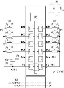
The following illustration shows the wiring diagram for the TM5SDO8TA:

1 Internal electronics
2 24 Vdc I/O power segment integrated into the bus bases
3 Inductive load protection
4 2-wire load
5 0 Vdc I/O power segment by external connection
6 PS1: External isolated power supply 24 Vdc(1)
7 External fuse, Type T slow-blow 8 A max., 250 V
(1) There is no connection between the module and the 24 Vdc I/O power segment on the bus base.
|
|
|
POTENTIAL OF OVERHEATING AND FIRE |
|
oDo not connect the modules directly to line voltage. oUse only isolating PELV systems according to IEC 61140 to supply power to the modules. |
|
Failure to follow these instructions can result in death, serious injury, or equipment damage. |
|
|
|
POTENTIAL EXPLOSION OR FIRE |
|
Connect the returns from the devices to the same power source as the 24 Vdc I/O power segment serving the module. |
|
Failure to follow these instructions can result in death, serious injury, or equipment damage. |
|
|
|
UNINTENDED EQUIPMENT OPERATION |
|
Do not connect wires to unused terminals and/or terminals indicated as “No Connection (N.C.)”. |
|
Failure to follow these instructions can result in death, serious injury, or equipment damage. |
Refer to Protecting Outputs from Inductive Load Damage for additional important information on this topic.