The TM5SPS2F Power Distribution Module feeds the TM5 power bus as well as the 24 Vdc I/O power segment through an integrated exchangeable fuse.
The table below describes the main characteristics of the TM5SPS2F electronic module:
|
Main Characteristics |
|
|---|---|
|
Maximum current provided on 24 Vdc I/O power segment |
6300 mA |
|
TM5 power bus current generated |
1136 mA |
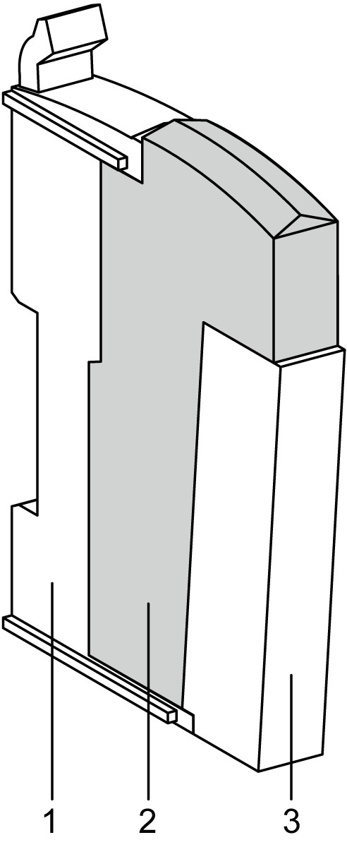
The following figure and table gives the references to create a slice with the TM5SPS2F electronic module:
|
Number |
Model Number |
Description |
Color |
|---|---|---|---|
|
1 |
TM5ACBM01R or TM5ACBM05R |
Bus base 24 Vdc I/O power segment left isolated
Bus base 24 Vdc I/O power segment left isolated with address setting |
Gray
Gray |
|
2 |
TM5SPS2F |
Electronic module |
Gray |
|
3 |
TM5ACTB12PS |
Terminal block, 12-pin |
Gray |
NOTE: For more information, refer to TM5 Bus Bases and Terminal Blocks.
The following figure shows the TM5SPS2F status LEDs:
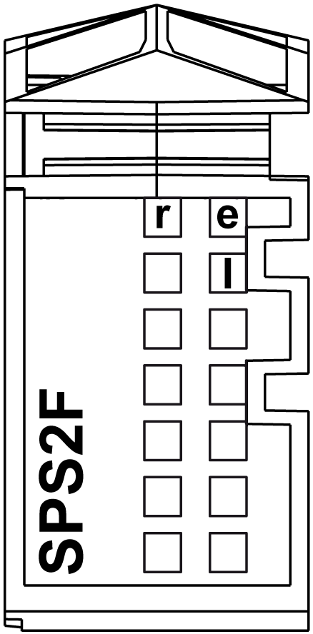
The table below describes the TM5SPS2F status LEDs:
|
LED |
Color |
Status |
Description |
|---|---|---|---|
|
r |
Green |
Off |
Power supply not connected |
|
Single flash |
Reset state |
||
|
Flashing |
Preoperational state |
||
|
On |
RUN state |
||
|
e |
Red |
Off |
OK or module not connected |
|
Double flash |
Indicates one of the following conditions: oTM5 power bus is overloaded. o24 Vdc I/O power segment, via the external power supply or supplies, is too low. oInput voltage for TM5 power bus, via the external power supply or supplies, is too low. |
||
|
e+r |
Steady red/single green flash |
Invalid firmware |
|
|
l |
Red |
Off |
TM5 power bus in the acceptable range |
|
On |
TM5 power bus is overloaded |
||