Internal modem connections
This section only applies if your meter has the internal 56k modem or cell modem option. Refer to the ION8650 Installation Guide for internal modem specifications and information on determining the options available on your meter.
NOTE: The internal cellular modem option is only available on the ION8650 socket meter.
56k universal internal modem
The 56k universal internal modem is accessed through COM2, supports all standard modem protocols at transmission rates from 300 bps to 57600 bps (300 bps is only recommended for paging applications) and can be shared by up to 31 devices on an RS-485 chain. It is available with a standard six-pin RJ-11 phone plug. If you have multiple meters linked on an RS-485 loop, only the first meter requires a 56k modem. This setup is referred to as a ModemGate (see Configuring ModemGate connections ). You can configure the settings of the 56k modem with the front panel, Power Monitoring Expert or ION Setup.
To enable communications through the meter’s 56k modem, configure the COM2 communications Baud Rate, Unit ID, Protocol, and ModemInit setup registers as required for your system. See Configuring ModemGate connections for more information on this register.
NOTE: When the meter is equipped with the Alert module, the modem can initiate calls. Paging is supported through numeric paging and the TAP1 protocol. See the Power Monitoring Expert online help for details on managing modem connections, setting up periodic dial-out and configuring remote site event notification.
ModemInit setup register
The ModemInit setup register defines the initialization string for the internal modem with a maximum of 47 characters. Edit the ModemInit register and enter the desired initialization string. The string is sent to the modem as soon as you download the COM2 module. Note that the string is also sent to the modem whenever the meter is powered up or the baud rate in the COM2 Communications module is changed.
NOTE: Changing the ModemInit or Baud Rate setup registers while the internal modem is online causes the modem to disconnect from the phone line.
Modem initialization strings
Refer to the Modem AT Commands technical note for a complete list of AT commands for meter modems.
NOTE: The Modem AT Commands technical note also contains instructions on how you can determine your meter’s modem type based on the meter’s serial number.
Adjusting the modem initialization string for CTR-21 compliant modems
The table below shows the strings to add to the end of your modem configuration string setup register for each of three possible scenarios.
| Behavior | Add to modem initializing string |
|---|---|
|
Does not answer (modem does not detect ring tone) |
*NC70 |
|
Does not dial (modem does not detect dial tone |
In order of preference: *NC70, *NC70X0, *NC8 (Italy only) |
| Does not detect busy signal | *NC70 |
If your local modem (not the internal modem) is not already set up, configure it with the Remote Modem Setup utility in Power Monitoring Expert according to the instructions in the online help. After the meter is installed and the internal modem is connected to the telephone network, the COM2 module can be configured using the meter’s front panel, Power Monitoring Expert or ION Setup. For information on how to connect the internal modem to the telephone network, refer to your ION8650 Installation Guide.
Configuring COM2 through the front panel
- Press and hold the ALT/ENTER button for a few seconds. The SETUP menu appears.
- Use the up or down arrow buttons to select COM2 SETUP and press ALT/ENTER.
- Configure the COM2 settings (for example, Baud Rate, Unit ID, and Protocol) to match your communications system.
Disabling the COM2 port using the front panel
You have the option of disabling the COM port through the front panel when the port is not being used.
- Press and hold the ALT/ENTER button for a few seconds. The SETUP menu appears.
- Use the navigation buttons to highlight the COM2 port and press ALT/ENTER to select.
- Use the navigation buttons to highlight the Protocol setting and press ALT/ENTER to select.
- Select Yes to confirm the change.
Configuring the meter and modem site using ION Setup
- Open the Setup Assistant for your meter. See the ION Setup Help for instructions.
- Select Communications > Serial Settings and click the COM2 tab.
- Select the setting that you want to configure and click Edit.
- Configure the COM2 settings (for example, Baud Rate, Unit ID, and Protocol) to match your communications system.
Disabling the COM2 port using ION Setup
You have the option of disabling the COM port through ION Setup when the port is not being used.
- Open the Setup Assistant for your meter. See the ION Setup Help for instructions.
- Select Communications > Serial Settings.
- Click the COM2 tab, select Protocol from the list and click Edit.
- Select None from the dropdown list and click OK.
Configuring the COM2 module using Designer
Before you can configure the COM2 module in Designer, you must add the meter (with the internal modem) and a modem site to your Power Monitoring Expert network.
Adding a meter and a modem site to your Power Monitoring Expert network
In Management Console, add the meter with the internal modem and a modem site to your Power Monitoring Expert network. Describe how your remote modem is wired and other communications information on the options screens.
Either before or after adding the modem site, you must add a dial out modem to the server computer. The server computer dial out modem communicates to the modem at the modem site.
On the Modem Site Options screen, ensure that you:
- Select the server computer that you want to communicate with the remote modem and that the server computer dial out modem is configured.
- Enter the remote modem telephone number.
- Set the baud rate of the modem site to the baud rate of the COM2 port to avoid communications errors.
See the Power Monitoring Expert online help for more information.
Configuring the COM2 Communications module in Designer
Start Designer and configure the COM2 Communications module Baud Rate, Unit ID, and Protocol setup registers to match your communications system. Configure the initialization string for the internal modem using the ModemInit register. Refer to ModemInit setup register.
Configuring ModemGate connections
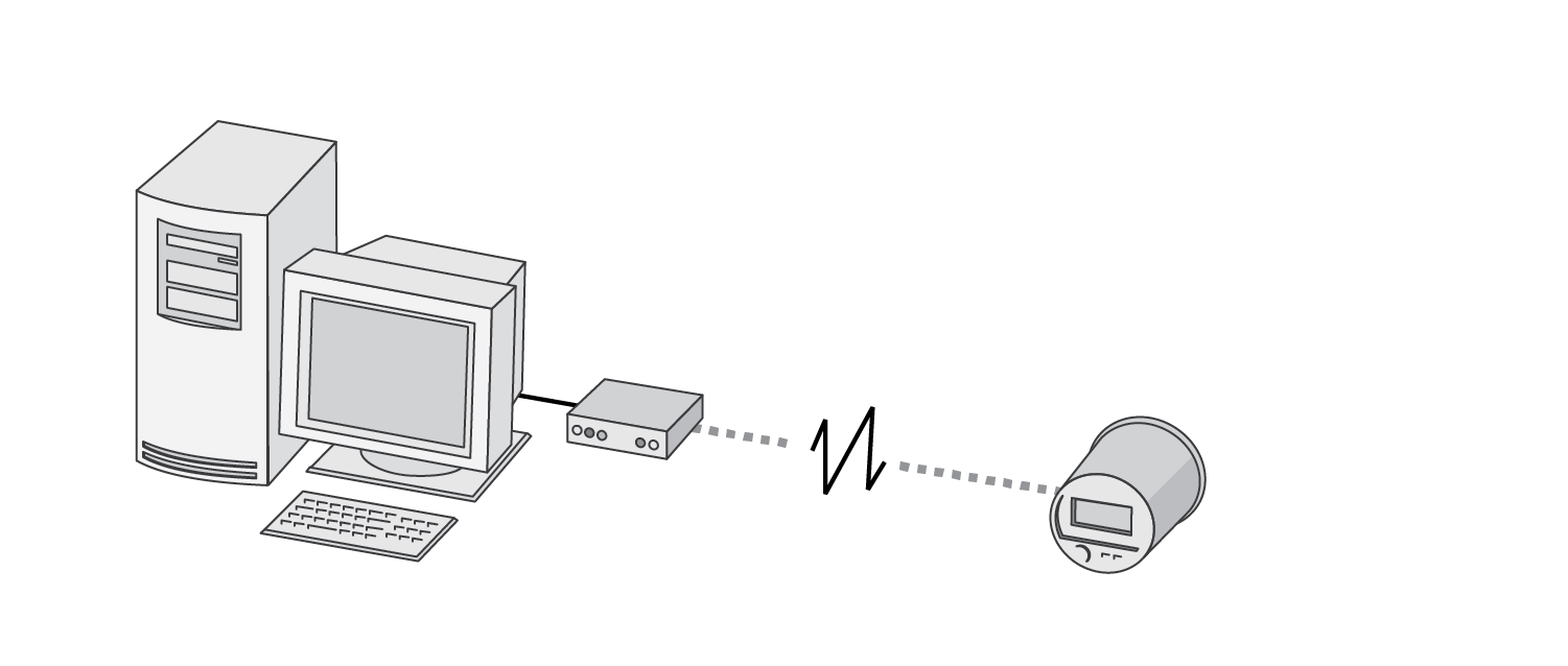
ModemGate is a powerful feature that creates a communications connection between the telephone network and an RS-485 serial network of devices. When you specify the protocol for a meter’s COM port as MODEMGATE, all data received by the meter’s internal modem is automatically transferred to the serial network. ModemGate is available on either the COM1 or COM4 port; you cannot use the feature on both ports simultaneously. The meter must have the COM2 modem option to function as a modem gateway.
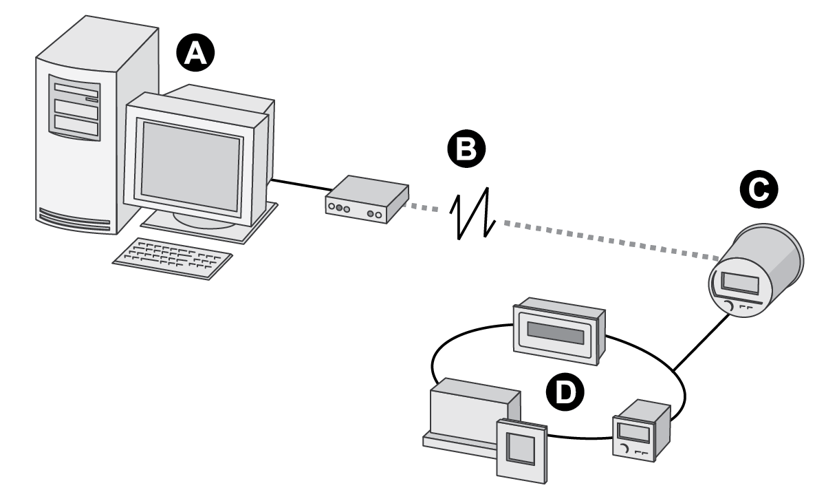
A | Workstation with Power Monitoring Expert and modem |
B | Telephone network |
C | ModemGate meter equipped with optional internal modem |
D | Devices on RS-485 loop |
NOTE: The baud rate used between connected modems is independent of the internal baud rate used for communication between the meter and its modem.
Wire a serial connection between one or more meters and the meter COM port hosting the ModemGate (COM1 or COM4). You can make ModemGate connections through an RS-232 cable to a single device or through an RS-485 shielded twisted pair cable to multiple devices. ModemGate connections do not connect a workstation running Power Monitoring Expert (or other master device) to the gateway meter’s COM1 or COM4 port, but rather to the gateway meter’s internal modem port (COM2); the meter then transfers the data to the serial devices connected to COM1 or COM4.
Configuring the meter for ModemGate
- Install the meter and connect the internal modem.
- Use the front panel, Power Monitoring Expert or ION Setup to set up the internal modem and the serial communications port (COM1 or COM4) that is the ModemGate. You can enable ModemGate on either COM1 or COM4, not both simultaneously.
- Set the internal modem COM2 Baud Rate, Unit ID and Protocol. The baud rate must be the same as the port hosting the gateway and all the devices connected to the gateway.
- Set the protocol of the port connected to the RS-485 loop to MODEMGATE (either COM1 or COM4). For each device on the RS-485 loop, you must also:
- Set the baud rate to the same value as the modem baud rate (COM2).
- Configure each device, including the gateway meter, with a unique Unit ID.
Configuring devices connected to the ModemGate meter
- Use Power Monitoring Expert, ION Setup or the front panel to change and configure settings. Ensure each device connected to the meter has the same baud rate as the meter ModemGate port (either COM1 or COM4)
- Ensure each device connected on the RS-485 network (including the meter modem) has a unique Unit ID. Record the serial baud rate of the modem site and the Unit IDs for every device in order to add the ModemGate and its meters to your network.
NOTE: Ensure RS-485 is selected for connections to multiple devices along the same bus.
Using ION Setup to create a ModemGate site
- Right-click on your workstation icon and select Insert Item. The New Network Item dialog box appears.
- Select Site and click OK. The New Site dialog box appears.
- Click the General tab.
- Configure the site as follows:
- Type a site name.
- Select Modem from the Comm Link options.
- Click Modem configuration to access the Modem configuration wizard, which configures your local and remote modems.
- Enter the phone number of the modem you are connecting to in the Phone Number field.
Click OK.
- Right-click on your newly created site and select Insert Item. The New Network Item dialog box appears.
- Select Meter and click OK. The New Device dialog box appears.
- Enter serial device information and click OK. Your new device appears under your newly created site.
- Repeat steps 5 to 7 to enter each device on your serial network.
Using Power Monitoring Expert to create a ModemGate site
To communicate to the devices on the RS-485 loop using Power Monitoring Expert:
- Start Management Console and create a Modem Site.
- Configure your modem site by typing in the appropriate fields or using the dropdown menus. Include the meter’s internal modem telephone number and ensure that the server computer’s dial out modem is configured. Refer to the online Power Monitoring Expert Help for information on adding a dial out modem.
Adding ModemGate meters to the Power Monitoring Expert network
- Start Management Console and click Devices. Right-click in the Devices display window and select New > Serial Device on Direct Site.
- Enter the information by typing in the appropriate fields or using the dropdown menus, remembering that:
- Unit ID: The value in the UNIT ID field identifies the meter on the RS-485 loop.
- Site: The ModemGate site that you created.
Internal cell modem
Configuration of the internal cell modem is accessible through the front panel and ION Setup.
Two modems are available: CDMA and LTE. The CDMA modem supports the EV-DO Rev. A and CDMA2000 1xRTT standards at transmission rates up to 3.1 Mbps downlink/1.8 Mbps uplink. The LTE modem supports Cat 1 LTE standards at transmission rates up to 10 Mbps downlink/5 Mbps uplink. Both modems allow for up to six simultaneous protocol data connections.
The cell modem requires network activation. For information regarding the network activation for your region and modem, refer to the PowerLogic ION8650 cell modem product option document.
NOTE: The 56k modem and cell modem exist as separate ordering options. You cannot have a 56k modem and a cell modem on the same device.