Serial connections
The ION8650 provides RS-232 and RS-485 serial communications connections, located on the back of the meter, as well as an optical port, located on the front of the meter.
Refer to the ION8650 Installation Guide for information on determining the serial port options available on your meter.
If the meter’s COM1 port is set to RS-232, you can connect this port to a remote modem, which in turn is connected to a computer. You must use a null-modem RS-232 cable to connect the meter to an external modem. One end of the cable must be equipped with a Micro-Fit 3.0 Molex female connector for mating with the Molex male connector on the meter.
You can connect numerous meters’ COM1 ports by selecting RS-485 and using an RS- 232 to RS-485 converter to create a serial network.
NOTE: You cannot use both RS-232 and RS-485 ports on the meter’s COM1 simultaneously.
You can configure your local and remote modems with Power Monitoring Expert or ION Setup. You can also use ION Setup or Power Monitoring Expert to schedule regular connection times to collect meter data.
Extension cables with Molex connectors are available for your meter. Pin assignments for the Molex connector are provided in the ION8650 Installation Guide that ships with the meter (also available at www.schneider-electric.com).
NOTE: The total number of possible serial connections is limited by the number of physical serial ports on the meter. The meter has two physical serial ports (not counting the front optical port).
RS-232 connections
Refer to the ION8650 Installation Guide for the meter’s RS-232 specifications and specific wiring instructions.
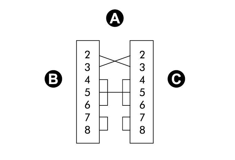
Because of the wiring configuration between pins 2 and 3, the meter is considered a DTE (Data Terminal Equipment) device in all RS-232 connections.
|
A |
DB9 null modem wiring diagram |
|
B |
DCE (computer) |
|
C |
DTE (meter) |
Communications settings for the RS-232 port are accessible through the front panel SETUP menu, Power Monitoring Expert or ION Setup.
Meter connections to single devices
|
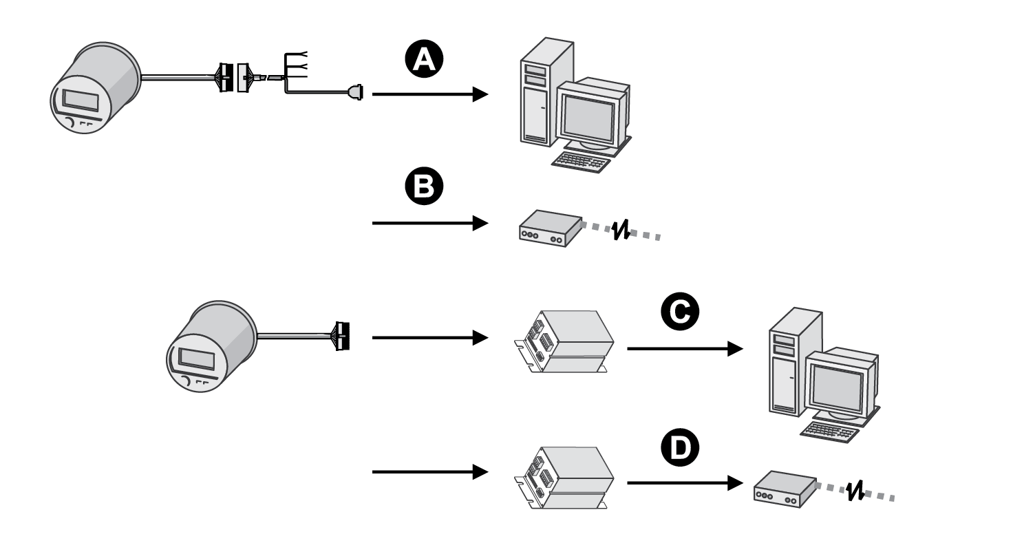
A |
DB9 direct connect to computer |
|
B |
DB9 direct connect to external modem |
|
C |
Molex direct connect to I/O Expander connected to computer |
|
D |
Molex direct connect to I/O Expander connected to external modem |
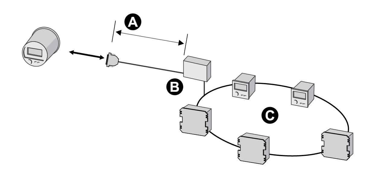
Meter connections to a serial loop
|
A |
RS-232 50 feet (15.2 m) maximum |
|
B |
RS-232 to RS-485 converter |
|
C |
RS-485 loop |
RS-485 connections
Refer to the ION8650 Installation Guide for RS-485 specifications and wiring instructions.
The breakout cable’s twisted pair provide connections for both of the meter’s RS-485 serial communications ports. The first set is for COM1 RS-485 connections. The second set is for COM4 RS-485 communications.
Up to 32 devices can be connected on a single RS-485 bus. Use a good quality shielded twisted pair cable for each RS-485 bus, AWG 22 (0.33 mm2) or larger. The overall length of the RS-485 cable connecting all devices cannot exceed 4000 feet (1219 m). The RS-485 bus can be configured in straight-line or loop topologies.
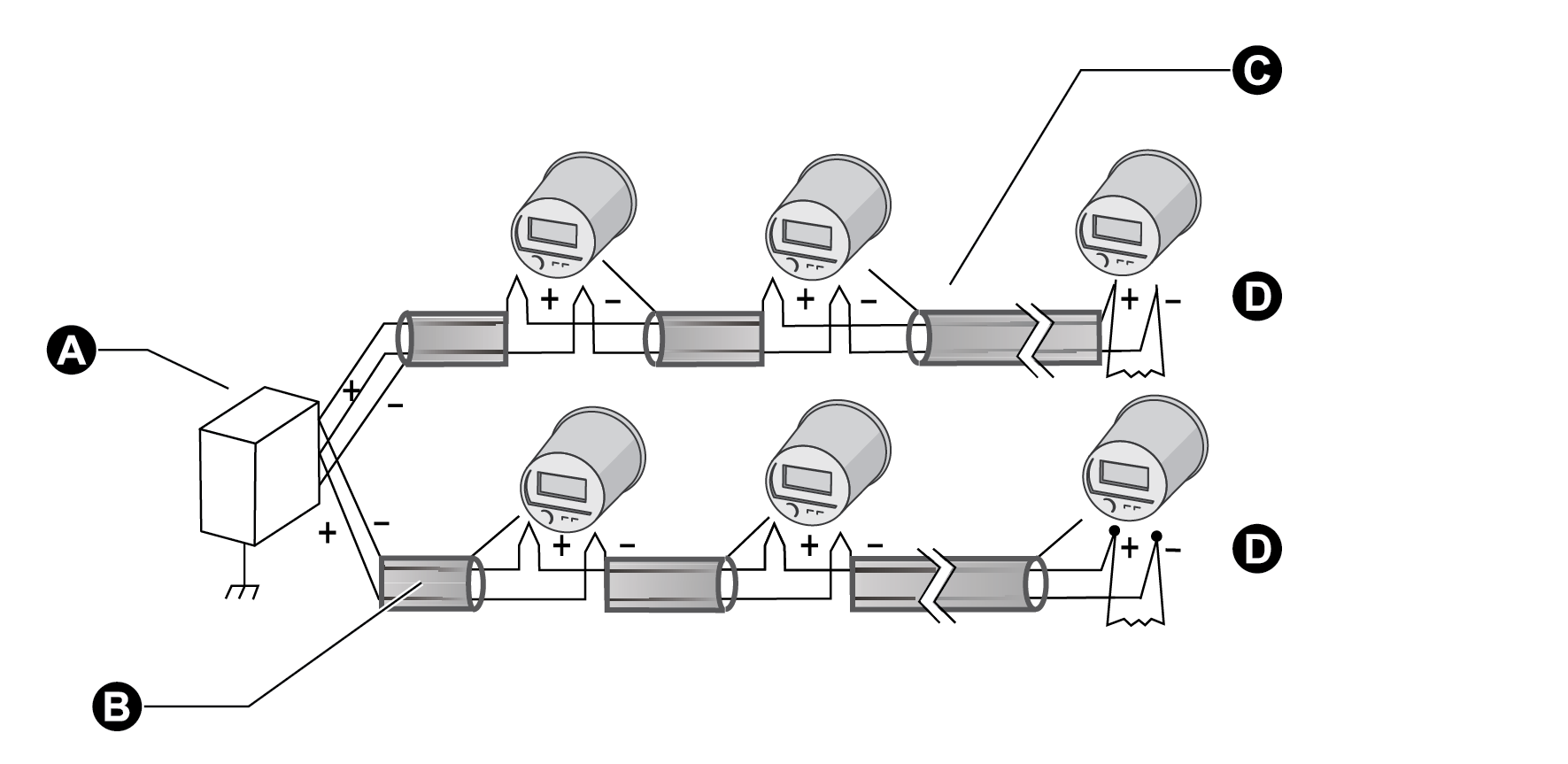
Straight-line topology
|
A |
RS-232 to RS-485 converter |
|
B |
Shield |
|
C |
Wiring color codes for the Molex cable are provided in the ION8650 Installation Guide that ships with the meter and is available at www.se.com. |
| D | Termination resistor |
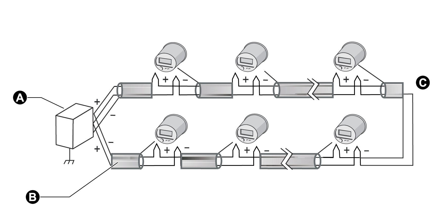
Loop topology
|
A |
RS-232 to RS-485 converter |
|
B |
Shield |
| C | Termination block |
General bus wiring considerations
Devices connected on the bus, including the meter, converter(s) and other instrumentation, must be wired as follows:
- Connect the shield of each segment of the cable to ground at one end only.
- Isolate cables as much as possible from sources of electrical noise.
- Use an intermediate terminal strip to connect each device to the bus. This allows for easy removal of a device for servicing if necessary.
- Install a ¼ Watt termination resistor (Rt) between the (+) and (-) terminals of the device at each end point of a straight-line bus. The resistor should match the nominal impedance of the RS-485 cable (typically 120 ohms – consult the manufacturer’s documentation for the cable’s impedance value).
RS-485 connection methods to avoid
Avoid any device connection that causes a branch in the main RS-485 bus. This includes star and tee (T) methods. These wiring methods can cause signal reflections that can lead to interference. At any connection point on the RS-485 bus, no more than two cables should be connected. This includes connection points on instruments, converters, and terminal strips. Following this guideline ensures that both star and tee connections are avoided.
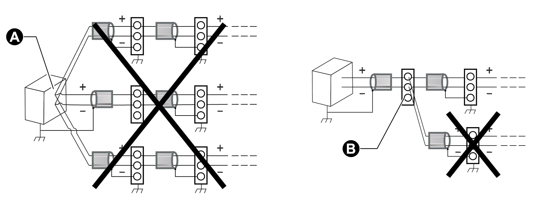
|
A |
Avoid 3-way 'Star' connection point |
|
B |
Avoid 3-wat 'T' connection point |
RS-485 biasing
The RS-485 +/- wires are floating (ungrounded) so there can be voltage signals on the wires even when there is no device communicating on the bus. The amount of floating voltage depends on many factors, such as capacitive effects in the RS-485 bus and noise in nearby systems. If the floating voltage is high enough, it can be incorrectly interpreted as an RS-485 signal and cause your meter to stop communicating. The meter has an RS-485 biasing option to prevent the RS-485 bus from floating when devices are not sending data.
Setting RS-485 biasing using the front panel
- Press and hold the ALT/ENTER button for a few seconds. The SETUP menu appears.
- Use the navigation buttons to highlight the RS-485 COM port that you want to configure (COM1 or COM4) and press ALT/ENTER to select.
- Use the navigation buttons to highlight RS-485 BIAS and press ALT/ENTER to select.
- Select either ON (RS-485 biasing applied) or OFF (RS-485 biasing not applied).
Setting RS-485 biasing using ION Setup
- Open the Setup Assistant for your meter. See the ION Setup Help for instructions
- Select Communications > Serial Settings.
- Click the COM1 or COM4 tab. Select RS485 Bias and click Edit.
- Select ON to apply RS-485 biasing or OFF to not apply RS-485 biasing.
- Click OK.
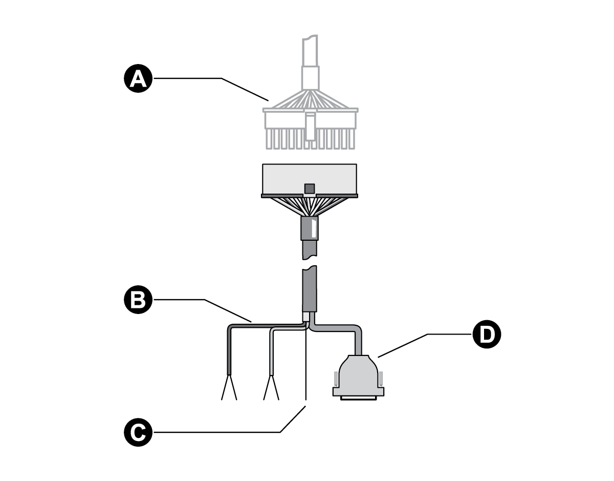
Communications breakout cable
Refer to the ION8650 Installation Guide for the DB9 serial pin assignments for the optional breakout cable female DB9 connector. A communications breakout cable facilitates communications connections by connecting to the Molex male connector on your meter. The cable splits to a standard DB9 female connector and two RS-485 shielded, twisted pairs.
|
A |
Molex male from the meter |
|
B |
Two RS-485 twisted pairs |
|
C |
RS-485 shield |
|
D |
DB9 female connector |
Configuring RS-485
Using the front panel
- Press and hold the ALT/ENTER button for a few seconds. The SETUP menu appears.
- Use the navigation buttons to highlight the RS-485 COM port that you want to configure (COM1 or COM4) and press ALT/ENTER to select.
- Configure the settings (for example, Protocol, Baud Rate and Unit ID) to match your communication system.
Disabling the COM port using the front panel
You have the option of disabling the COM port through the front panel when the port is not being used.
- Press and hold the ALT/ENTER button for a few seconds. The SETUP menu appears.
- Use the navigation buttons to highlight the RS-485 COM port that you want to configure (COM1 or COM4) and press ALT/ENTER to select.
- Use the navigation buttons to highlight the Protocol setting and press ALT/ENTER to select.
- Select None from the list of available protocols.
- Select YES to confirm the change.
Using ION Setup
- Open the Setup Assistant for your meter. See the ION Setup Help for instructions.
- Select Communications > Serial Settings.
- Click the COM1 or COM4 tab and configure the settings (for example, Protocol, Baud Rate, and Unit ID) to match your communications system.
Disabling the COM port using ION Setup
You have the option of disabling the COM port through ION Setup when the port is not being used.
- Open the Setup Assistant for your meter. See the ION Setup Help for instructions.
- Select Communications > Serial Settings.
- Click the COM1 or COM4 tab, select Protocol from the list and click Edit.
- Select None from the dropdown list and click OK.
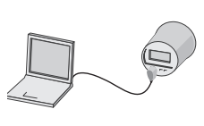
Configuring the optical port
Refer to the ION8650 Installation Guide for optical port specifications.
The optical port available on ION8650 meters is compatible with standard magnetic optical communications couplers, or optical probes (ANSI Type II). Optical probes are available both from Schneider Electric and other suppliers as a separate product; contact Schneider Electric for a list of suppliers. The original equipment manufacturer’s warranty applies. See the Optical Magnetic Couplers technical note for more detailed information.
Optical probes can communicate real-time measurements via the ION, RTU, DLMS, DNP 3.0, Factory, or GPS protocols. You can configure the optical port communications settings with the front panel, Power Monitoring Expert or ION Setup.
Using the front panel
- Press and hold the ALT/ENTER button for a few seconds. The SETUP menu appears.
- Use the up or down arrow buttons to select COM3 SETUP.
- Press the ALT/ENTER button to access COM3 SETUP parameters.
- Configure the settings (for example, Baud Rate, Unit ID, and Protocol) to match your communications system.
Disabling the COM port using the front panel
You have the option of disabling the COM port through the front panel when the port is not being used.
- Press and hold the ALT/ENTER button for a few seconds. The SETUP menu appears.
- Use the navigation buttons to highlight the optic port (COM3) and press ALT/ ENTER to select.
- Use the navigation buttons to highlight the Protocol setting and press ALT/ENTER to select.to select.
- Select None from the list of available protocols.
- Select YES to confirm the change.
Using ION Setup
- Open the Setup Assistant for your meter. See the ION Setup Help for instructions.
- Select Communications > Serial Settings.
- Click the COM3 tab and configure the settings (for example, Baud Rate, Unit ID, and Protocol) to match your communications system.
To enable communications from the optical port, you must configure the COM3 communications. The Protocol, Baud Rate and Unit ID settings must properly match your system. When creating a site, ensure RTS Control setting is disabled for the COM3 serial site.
Disabling the COM port using ION Setup
You have the option of disabling the COM port through ION Setup when the port is not being used.
- Open the Setup Assistant for your meter. See the ION Setup Help for instructions.
- Select Communications > Serial Settings.
- Click the COM3 tab, select Protocol from the list and click Edit.
- Select None from the dropdown list and click OK.
Using Power Monitoring Expert
- Open Management Console and add a Direct Site.
- Set the Serial Port to COM3 and ensure that the settings properly match your system. Ensure that RtsCts is disabled for the optical port site in Management Console. Refer to the Management Console section of the online Power Monitoring Expert help for details.