Deploying and configuring a Multi-input Setpoint Display Bar graphic component
You can create and deploy a Multi-input Setpoint Display Bar graphic component in the Graphics Editor, and then bind and view the graphic object in Building Operation Workstation.
To create the graphic component:
- Navigate to:
<Extract path>\EBO Integration Files\Graphics Editor\Components\and double-click the " PME- Generic Components" file. The new thermometer graphic component is added to the Building Operation Graphics Editor library. - Open the Building Operation Graphics Editor.
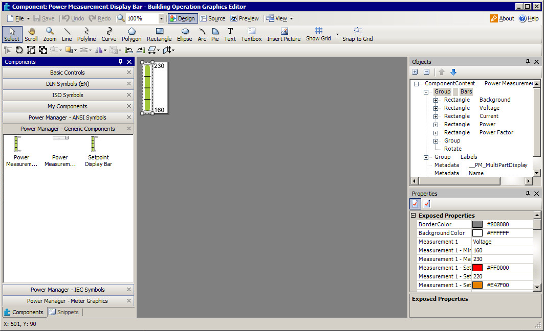
- From the PME– Generic Components category at the left, drag the Power Measurement Display Bar component onto a new page. The Multi-input Setpoint Display Bar component appears.

- Select the component. In the Properties pane at the lower right, change the parameter settings as needed (name, min/max, setpoint values, and so on). Make sure that the settings make logical sense (for example, all setpoints are within the min/max range and in the following order: SP4>SP3>SP2>SP1).
- Save the new graphic component page as a .tgml file.
To deploy the graphic component:
- Log in to Building Operation Workstation.
- In the System Tree, select a Server, and then choose File > New > Graphic, enter a name for the file, and click Create. The new graphic file name appears in the System Tree.

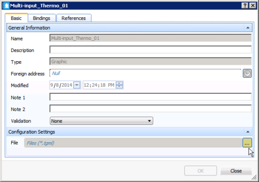
- In the System Tree, right-click the graphic file name and select Properties.
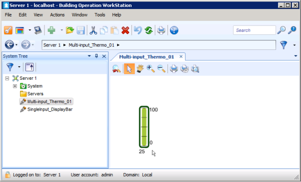
- In the Basic tab, click the button next to the File field and navigate to the .tgml file, select the file, click Open and then OK. The Multi-input Setpoint Display Bar now appears in the Building Operation Workstation.

- In the System Tree, select the Server, and then choose New > Value. The Create Object dialog appears. Repeat the above steps four times to create four new values.
- Select Analog Value and complete the fields for Name, Location, and Description as needed, and then click Create for each new value. The four new Analog Values now appear.
- For each value, double-click the name after adding it. Click the up or down arrows to select a number, and then click the Value button to select Forced or Force value for the object. Click Yes to save the object.
- To bind the graphic object to the value you just created, in the System Tree, right-click the graphic file name and select Properties.
- In the Bindings tab, enter the location of the graphic object in the object value field and click OK. The Multi-input Setpoint Display Bar now shows the preset setpoint values and bound values. The reading bar height and color change accordingly.
To verify the bind of the graphic component:
- In the System Tree, right-click on the new graphic file name and click Edit. The Graphics Editor opens.
- Revise some graphic component parameters (for example, min/max, setpoint values, or colors), save the file, and return to Building Operation Workstation. Your changes appear on the Graphics page in Building Operation Workstation.