Using ION modules
You can change the function of a node by editing the appropriate module(s) in the node diagram and linking modules together.
This section describes how to locate an existing module, how to add a new module, and how to delete a module. It also explains how to create a shortcut to a module and how to view the contents of a module in text format.
After you have located or added the module you want, you can configure it using the procedure described in Linking ION modules.
Using the ION modules toolbox
The ION Modules toolbox is a collection of ION modules and generic tools that you can add to a node diagram. To display the ION Modules toolbox, select Options > Show Toolbox.
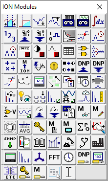
The type and quantity of modules offered on the toolbox varies depending on the type of node you are configuring; however, the generic tools (the grouping and text objects) are available for all nodes.
NOTE: To identify a module in the toolbox, point to it with the mouse—the module type is displayed as a ToolTip and on the status line at the bottom of the screen.
To add a module to your node diagram (and to the node itself), drag its icon from the toolbox into the diagram window.
Opening the ION modules toolbox
To open the toolbox, select Options > Show Toolbox.
Closing the ION Modules Toolbox
Click the Close button  or clear Options > Show Toolbox.
Locating an existing ION module
Before you can edit a module, you must first locate it in the node diagram. To find a module in a node diagram, you can use the module tray feature of the toolbox.
Locating an existing module from the Module Tray
-
To display the module tray, right-click the toolbox icon for the type of module you want to locate. The module tray appears beside the toolbox.
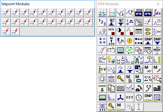
The module tray displays links to all modules of that type that are currently in use on the node—for example, in the image above, there are 22 Setpoint modules in use by the node. To identify a link in the tray, point to it—the module's label is displayed on the status line at the bottom of the screen.
- To locate a particular module, click its link in the module tray. Designer locates the module and displays it in the center of the workspace. If the module is located inside a grouping window, Designer opens the window to display the module.
TIP: To close the module tray, click on any module icon in the toolbox.
Adding a new ION module
Most nodes are pre-programmed at the factory to provide the most commonly required functions. However, if the factory default configuration is not appropriate for your application, you can add a new module.
Adding a module on a node
Drag the icon of the module you want to add from the toolbox onto the node diagram.
As you drag the icon, the cursor changes shape to indicate you are placing an object.
Designer adds the module and places a pending module icon into the diagram. You can then link and configure the module.
See Linking ION modules for more information on programming modules.
Deleting or cutting an ION module
To remove a standard module from a node, delete its icon from the node diagram. By removing unnecessary modules from the node, you can free up resources for use elsewhere.
notice
unintended device operation
Do not delete any ION modules without knowing which modules are dependent on it.
Failure to follow these instructions can result in the unintended operation of the remaining modules.
NOTE: Each time a module is deleted, all of its output registers, setup registers and input links are deleted as well. Removing this information from the node affects the operation of any modules that depend on it. For this reason, you should be aware of all dependent modules (also known as owners) before you delete anything.
Checking for dependent modules
When two linked modules are located in the same window, Designer depicts the link as a line that runs from the output register of one module to the input of another. You can easily identify the dependent module (or owner) by the line running to its input. However, if one of the linked modules is located in a different window, the connection is not visible. A more effective way to locate a module's owners is to view the owners of its registers.
Viewing the owners of a module's setup and output registers
You can view a register's owners to quickly identify all dependent modules on the node. You can determine what purpose the modules serve, and then decide whether to delete them or not.
- Do one of the following to open the Owners dialog:
- To view the owners of a module’s output registers, right-click the output symbol.
To view the owners of a module’s setup registers, hold the CTRL key and then right-click the output symbol.
The dialog lists all of the module's registers and any dependent modules on the node (dependent modules on other nodes are not displayed).
- Click a register in the Registers list to display the owners of that register in the Owners list on the right. Owner information includes the module name or label and its relevant input.
- If necessary, delete the link between a register and one of its owners. Select the owner from the Owners list and click Unlink. (See Deleting links for more information on deleting module links.)
- When you have finished viewing the register owners, click OK.
Viewing owners on other nodes
Displaying a module's register owners is an effective way to locate dependent modules on the selected node but it does not show any dependent modules located on another node.
If you remove a module with a dependent module on another node, the dependent module's inputs are not reset. It continues to look for the deleted output register.
If you are not sure whether a module has dependents on other nodes, check with the person who programmed them to ensure you do not disrupt the operation of any modules on that node. If you still want to remove the module, you may want to directly delete the link on the other node first. In this way the module is not inadvertently linked to the next module to occupy the location of the deleted module.
Deleting or cutting an ION module
After you have determined that you can remove an ION module without disrupting other functions, there are two ways to remove it: delete and discard the module or cut the module to paste it in another location.
In either case, Designer immediately removes the icon from the node diagram and deletes the module from the node. The difference is, when you delete a module, it is discarded; when you cut a module, it can be restored (by selecting Edit > Paste).
NOTE: You do not have to select Send & Save Changes to delete a module. Designer immediately removes the module from both the diagram and the node.
Removing an ION module from the node
- Select the icon(s) of the module(s) you want to remove.
- Do one of the following:
- To cut the module(s) to paste it in another location, select Edit > Cut.
To discard the module(s), press the Delete key.
notice
unintended device operation
Do not delete any ION modules without knowing which modules are dependent on it.
Failure to follow these instructions can result in the unintended operation of the remaining modules.
NOTE: If a module has a dependent module on another node, Designer does NOT alert you of the dependency when you delete it. Before you delete a module, ensure that you are aware of all links to modules on other nodes.
Designer displays a summary of the proposed changes.
The summary lists all selected modules, and identifies those in the selection that will be deleted (including those with dependents on that node) and those that will not. Select a module in this list to display any additional information available in the field at the bottom of the dialog.
-
Click OK to remove the selected modules (or Cancel to abort the procedure).
Designer removes the module icon from the node diagram and deletes the module from the node itself.
NOTE: If you delete a shortcut icon, the original module is not affected. However, when you delete the original module, all shortcuts to that module are also deleted.
Viewing a node or module as text
You can use the View Diagram Text command to display as text the complete contents of one or more modules or of an entire node. Use this option to view the specified information on your screen so you can sort it, perform analysis, create a detailed record of your node’s configuration, or print a copy for your records.
-
Select the module(s) that you want to display.
TIP: To select all modules in the node, left-click on the background of the main node window, being careful not to click on a module icon, then select Edit > Select All.
-
Select Options > View Diagram Text to open the Text View screen. The text of any modules that are offline appears in red.
- The Text View screen offers several ways to view, sort and find information:
-
In the View dropdown list, select one of two view modes:
- Use Archive to display information useful for archiving the node's configuration.
- Use Diagnostic to display diagnostic information on the selected module(s).
-
In the Sort by dropdown list, select the criteria by which you want to sort the data:
Archive View Diagnostic View Sorts by Default Default Module label Module Class Module Class Type of module Module Name Module Name Default label Module State Displays offline modules first followed by online modules. Sorts alphabetically within each group. Module Update Period Displays event driven modules first, then inactive (not updating) modules, followed by high-speed (one cycle updates) modules, and finally high-accuracy (one second updates) modules. Sorts alphabetically within each group. - In the Find text field, type a text string and click Find to find that text string in the data.
To reset the text view after you have made a configuration change, click Refresh. If you want to print a copy of the text view information, click Print. When you are finished viewing the text view information, click Close.
Creating a shortcut to an ION module
To save time switching between modules in different windows, create a shortcut icon in one window that represents the original module in the other window.
A shortcut icon is identified by a ![]() symbol in the lower left corner of a module icon.
symbol in the lower left corner of a module icon.
Creating a Shortcut Icon
Hold down SHIFT+CTRL then drag the module icon(s) to the window where you want to place the shortcut(s).
After you have created a shortcut icon, you can use it in the same way you use the original module icon. Both icons support the same features. However, if you delete the shortcut icon, the original module icon is not deleted; whereas if you delete the module icon, it deletes all shortcuts to that module.
NOTE: You cannot create more than one shortcut icon per window for a single module.
Adding a text box to a node diagram
You can place a text box anywhere in a node diagram, and move it or resize it as necessary. You can use a text box to describe any process or function in your system; for example, you can label individual components of your system or display a block of descriptive text or instructions.
Adding a Text Box
-
Drag a Text Box object (
 ) from the toolbox onto the node diagram.
A text box opens in the diagram with the default message: “Your text goes here.”
- Right-click the text box to replace the default text with your own text. The Text Box Configuration dialog opens.
- Select the Edit Text tab, then do one of the following:
- To display the name of the node in the text box, select Use Default.
- To display your own message, select Use Custom and type your text into the field provided.
- Click OK. The text box displays your specified text.
Resizing a Text Box
To resize a text box:
- Select the text box.
- Do one of the following:
- To make the object larger or smaller, drag a corner handle.
- To stretch the object horizontally or vertically, drag a middle handle.
Changing the font of a Text Box
The font, size and style of the text used in the text box is based on the default setting specified for the active window. If you want to use a different font, you can specify a new font for the text box:
- Right-click the text box to open the Text Box Configuration dialog.
- Select the Text tab.
- In the Font section, do one of the following.
- To use the font specified for the parent window, select Inherit from parent window.
- To use a different font, select Custom, then click Font to open the Font dialog. Specify a font, style, and size. Click OK to continue.
- Click OK.
Changing the position of the Text
To change the position of the text in the text box:
- Right-click the text box to open the Text Box Configuration dialog.
- Select the Text tab.
- In the Position section, select Left, Center, or Right.
- Click OK.
Adding a border or background color to a Text Box
To add a border to a text box or change its background color:
- Right-click the text box to open the Text Box Configuration dialog.
- Select the Box tab.
- Do one or more of the following:
- To add a border, select Show in the Border section and click Color to select a border color.
- To set the width of the border, type a border width in the “Width in pixels” field in the Border section.
- To add a background color, select Custom in the Background Color section and click Color to select a background color.
- Click OK.