EPSS diagrams
NOTE: These diagrams are part of the Backup Power Module. This Module requires a separate license. The module must be configured before the diagrams can be used.
Overview
The diagrams show status and operational details for the generators and transfer switches that are part of the EPSS system.
Diagrams
EPSS diagrams are organized into 3 levels:
- Groups summary page
- Group details pages
- Device details pages
In addition, there are summary pages for all the generators and all the transfer switches in the system.
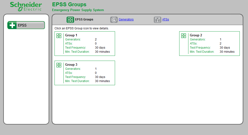
1. Groups summary page
This page shows a summary for each EPSS group.
Example groups summary page:
2. Group details page
This page shows details for each generator and transfer switch device in the group.
TIP: Click the group icon for a group in the groups summary page to open the respective group details page.
Example group details page:
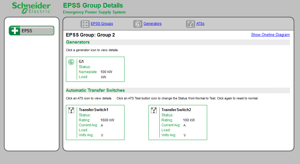
(No data is shown in this example because the diagram is not linked to actual devices.)
3. Device details page
This page shows details for a specific generator or transfer switch device.
TIP: Click a device icon for a generator or transfer switch in the group details page to open the respective device details page.
Example device details page:
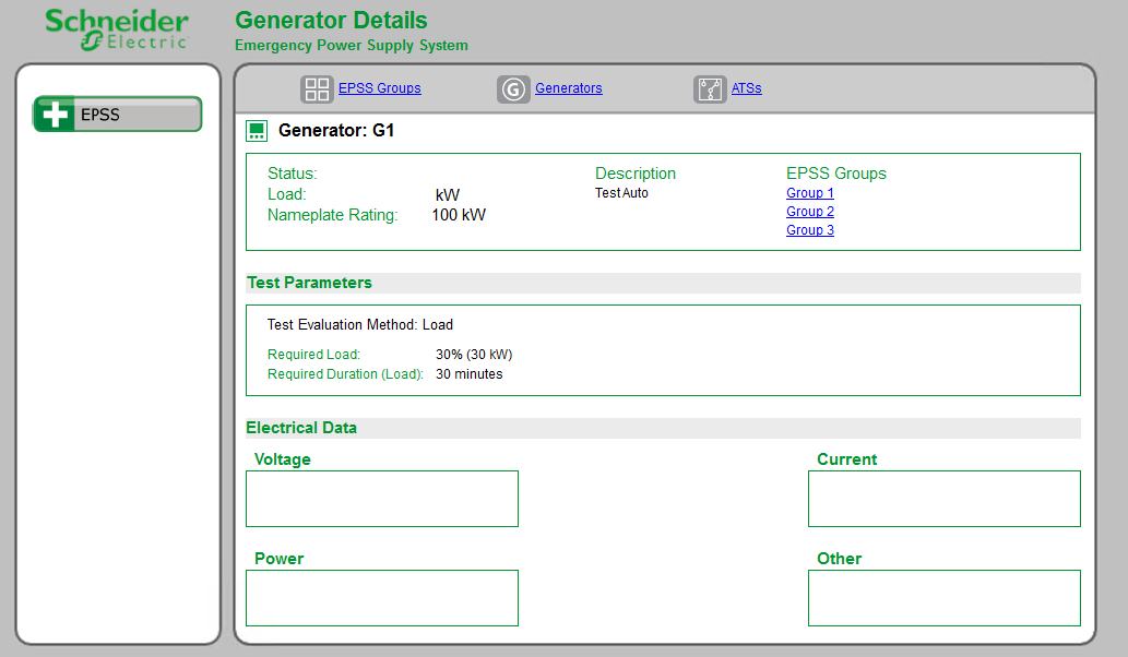
(No data is shown in this example because the diagram is not linked to actual devices.)
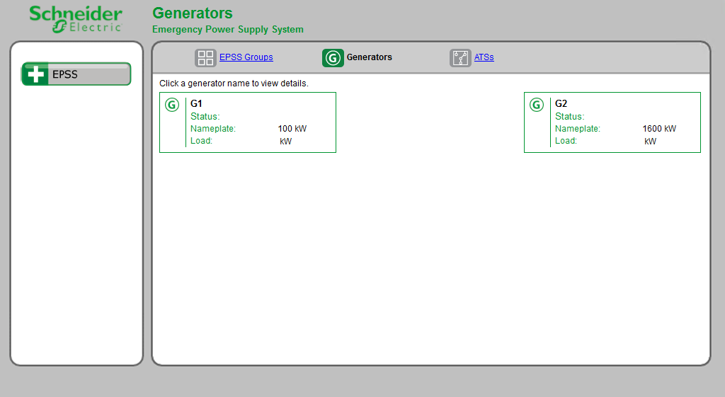
Summary pages
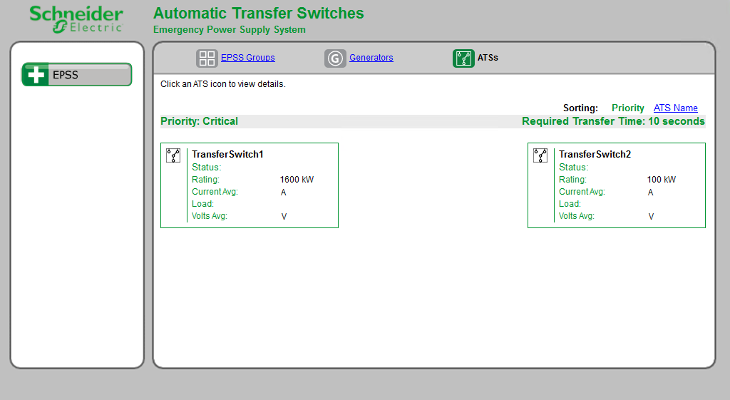
These pages show details for all the generators and all the transfer switches that are defined in the system.
Example generator summary page:
Example transfer switch summary page:
Related topics:
- The Diagrams user interface
- User authentication
- Viewing historical (trend) data
- Viewing meter events
- Viewing user diagram of devices with security
- Performing manual control actions
- Stale data and error indicators
- Power Quality Performance diagrams
- Insulation Monitoring diagrams
- UPS Auto Test diagrams
- EPSS diagrams
- Breaker Aging diagrams
For information on how to configure Diagrams, see Diagrams and graphics configuration.